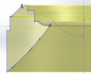
No discontinuity in height between the cone and tweeter/phase plug that i can see or feel with my finger. Other than space between them, of course.
View attachment 1001503
Thanks Zvu, quotation works well.

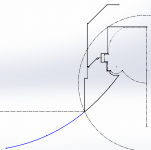
Looks nice - driver with shadow flare. If you are interested in another TW in coax, at the end of road, I'll have .stl for Peerles (or another one TW). As I can see, you have 3D printer so you can try it too. The question is if geometry insde R driver is same as in Q300 case...?
I posted some simulation results for a similar tweeter in the WG formed by the mid cone somewhere on the very first pages of this thread. (post #26) The results were not very promising in comparison with a dome tweeter without a radiating surround, mainly because of a very pronounced on-axis dip. The simulations were not very comprehensive, though. Anyway, this is a issue which can be quite easily investigated using Ath and ABEC in circular symmetric geometry. Perhaps you could play with some additional 3D-printable structures for covering the dome surround?
I can post here some drawings of new flange for Peer 3/4". I think that is goal to cover surround, as you say. Original KEF design is the same. I want to try two designs - without tangerine and with it. Now I'm fighting with 3D model, it's a complicated shape...
I can post here some drawings of new flange for Peer 3/4". I think that is goal to cover surround, as you say. Original KEF design is the same. I want to try two designs - without tangerine and with it. Now I'm fighting with 3D model, it's a complicated shape...
Please do. At least I'm very much interested. Actually, I could edit the thread title a bit to expand the topic UniQ related experiments in general.
Zvu:
Tweeter is Peerless OX20SC00-04, stv you're right. It's only 3/4" but I hope it will act good in midbass cone profile. Maybe mesurements shows unexpected problems. I would like to simulate TW in this specific conditions to avoid trial-and-error method. 🙂
Consider using the ring radiator version of that tweeter instead: Peerless/Vifa OT19NC00-04 | somasonus. It will behave better. If you you must use the dome version, look at my results for the SB Acoustics SB19 and SB21 to get idea of how it will probably look. BTW, you can only iterate the designs because modeling a flexible fabric dome is not going to happen with the tools DIYers have available. My work with ATH/ABEC shows the results only match reality for the metal domes.
That's a very good point. Accounting for the soft dome breakup would require a multiphysics approach with specific input data for the mechanical properties of the fabric dome.
Last edited:
Consider using the ring radiator version of that tweeter instead: Peerless/Vifa OT19NC00-04 | somasonus. It will behave better. If you you must use the dome version, look at my results for the SB Acoustics SB19 and SB21 to get idea of how it will probably look. BTW, you can only iterate the designs because modeling a flexible fabric dome is not going to happen with the tools DIYers have available. My work with ATH/ABEC shows the results only match reality for the metal domes.
Hi Brandon,
Your work on measuring different TW drivers in various waveguides is very beneficial, thanks for link to your website. In fact I have decided between Peer/Vifa OX20 and OT19, and I bought OX20. I don't see problem to order ring radiator OT19, if I'll not satisfied with measurements. If soft dome TW's are hard to simulate in ABEC, all I have to do (as Zvu says), is print the adapter for the OX20 and test how it will behave during the measurement - in my opinion.
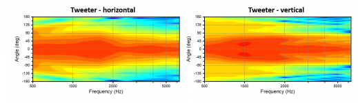
Yeah, just try it. Perhaps ABEC simulations can still shed some light in case the experiments show very strange results... That being said, it would be extremely interesting to see how a ring radiator would perform in the middle of a UniQ cone, since they seem to be quite good match with many waveguides. I don't think I have ever seen a coax with such tweeter in the middle.
I just couldn't resist... It was pretty straightforward to set up a Comsol BEM model for the woofer-coax-woofer speaker with the Fusion 360 model already at hand. I still have to do some refinements, but here are some results with woofers replaced by planar surfaces.

2dB steps
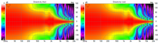
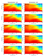
Here's VituxCAD for the mid for comparison. Same baffle dimensions, but without any edge rounding or shaping for diffraction control.
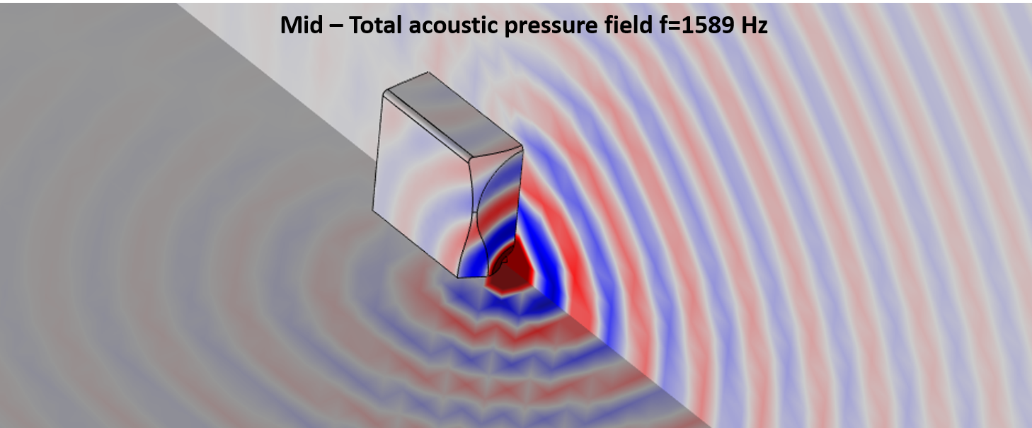
Some similarities, some differences, some thinking needed... Finally, the pressure field for the mid at 1.5kHz, where the most significant diffraction features are observed. I think I have to play a bit with the enclosure dimensions and perhaps add some structure to model the effect of woofers on mid/tweeter response.
2dB steps
Here's VituxCAD for the mid for comparison. Same baffle dimensions, but without any edge rounding or shaping for diffraction control.
Some similarities, some differences, some thinking needed... Finally, the pressure field for the mid at 1.5kHz, where the most significant diffraction features are observed. I think I have to play a bit with the enclosure dimensions and perhaps add some structure to model the effect of woofers on mid/tweeter response.
Attachments

Last edited:
I think first I have modify the chamfer around the driver. Now there's too many lambda/2 sized dimensions for 1.5kHz.
It was pretty straightforward to set up a Comsol BEM model for the woofer-coax-woofer speaker with the Fusion 360 model already at hand. I still have to do some refinements, but here are some results with woofers replaced by planar surfaces.
Looks like pretty useful stuff once you have established it is reliable. How are you representing the tangerine phase plug/waveguide?
Finally, the pressure field for the mid at 1.5kHz, where the most significant diffraction features are observed.
It may be the plotting but are those features resolved?
I think I have to play a bit with the enclosure dimensions and perhaps add some structure to model the effect of woofers on mid/tweeter response.
I had started preparing for something similar using open source software but it stalled when the manual for the BEM code seemed to indicate I would need to use a half rather than a quarter model. The reason appeared to be incomplete implementation of symmetry BCs under some circumstances but not others. Odd. Whatever, looking forward to seeing more of your BEM simulations which I suspect are going to be a requirement for reliable simulations given how much is going on.
Consider using the ring radiator version of that tweeter instead: Peerless/Vifa OT19NC00-04 | somasonus. It will behave better. If you you must use the dome version, look at my results for the SB Acoustics SB19 and SB21 to get idea of how it will probably look. BTW, you can only iterate the designs because modeling a flexible fabric dome is not going to happen with the tools DIYers have available. My work with ATH/ABEC shows the results only match reality for the metal domes.
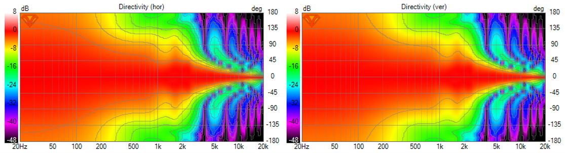
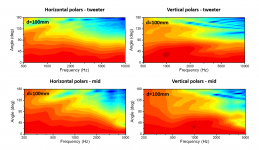
I made a little comparison picture with manufacturers frequency response of drivers. I think OX20 gives better off axis respones. What do you think? Is the key WG loading? In my opinion at high frequencies (10kHz+) is WG without effect.
Attachments

The results on a waveguide won't look anything like that. You'll have to make the actual measurements to know for sure how it will react.
Looks like pretty useful stuff once you have established it is reliable. How are you representing the tangerine phase plug/waveguide?
I haven't tried to implement the tangerine phase plug in any way. I just hope that it doesn't significantly affect the response of the surrounding mid cone in terms of the baffle/enclosure related features. I'm not so much interested in the HF response of the tweeter here.
It may be the plotting but are those features resolved?
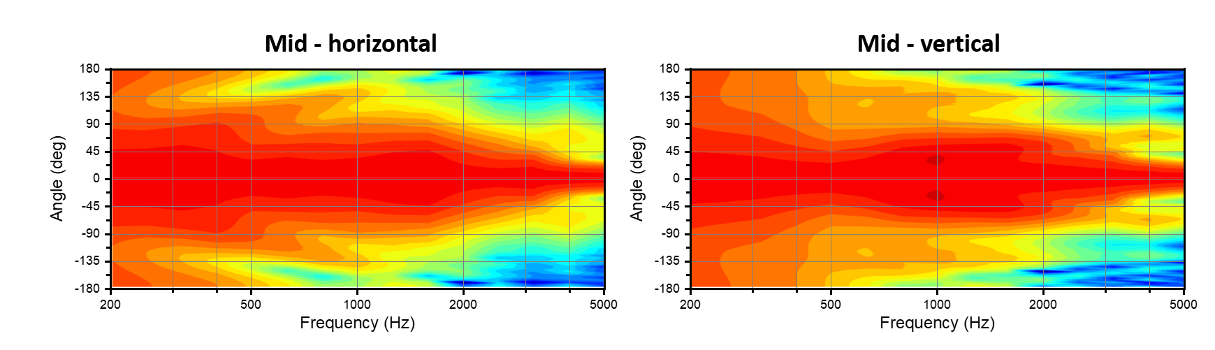
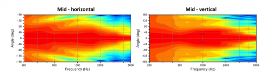
I suppose it's not very clear in those plots, but I'm talking about the general widening of the response at around 1.5 kHz in the horizontal plots. I'm not ready to make any conclusion yet based on the more complex stuff visible in the vertical plots. Let's first see how much of that is grid-independent.
I had started preparing for something similar using open source software but it stalled when the manual for the BEM code seemed to indicate I would need to use a half rather than a quarter model. The reason appeared to be incomplete implementation of symmetry BCs under some circumstances but not others. Odd. Whatever, looking forward to seeing more of your BEM simulations which I suspect are going to be a requirement for reliable simulations given how much is going on.
That's unfortunate and undoubtedly frustrating. All symmetries are indeed more than welcome in complex 3D problems.
I believe this is reliable data. The model is for 90deg symmetry and includes around 10000 mesh elements and 15000 degrees of freedom. Solving for 15 frequency points from 200 to 5000 Hz takes a couple of hours (i7-8650U, 32GB RAM). I think a coarser mesh would have been sufficient for lower frequencies, but in the end it's the computer doing the heavy lifting while I do other stuff.
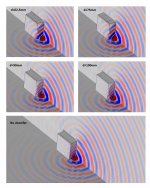
The pressure maps are for f=1589Hz. They are shown for illustrating the different cabinet shapes. One is for no chamfer and the others I varied the parameter d, which is the lateral distance from the center of the driver to the point where the chamfer starts. So small d means large chamfer.
The interesting stuff is in the horizontal polar around 1.5-2kHz.* Without chamfer the widening is closer to 2kHz as predicted by VCAD as well. At the opposite end is the largest chamfer (d=62.5mm) which extends all the way to the driver edge. Here the widening is closer to 1.5kHz. The smoothest directivity in this range is observed for smaller chamfers (d=90 or 100mm).
So the largest possible chamfer is not always the optimal. This is most likely because it creates a new facet and we should consider the dimensions of these facets together with the other enclosure dimensions such as width and driver size. There's diffraction from both edges of the chamfer. In this respect, roundover is probably safer choice if executed without modeling or experimentation.
I should also thank Andy for gently pushing me to this direction. It's probably not a surprise to you that my initial choice of d was not the optimal one😀
*I hope that the color contrast between the most intense contours is displayed well enough on your screens. Removing the grid lines seems to have helped at least my eyes/brain.
Attachments
I believe this is reliable data. The model is for 90deg symmetry and includes around 10000 mesh elements and 15000 degrees of freedom.
Are you using triangular, quad or a mixture of elements? Are they generated with or without a pattern? What is the order of the element and the number of elements per wavelength?
The pressure maps are for f=1589Hz. They are shown for illustrating the different cabinet shapes. One is for no chamfer and the others I varied the parameter d, which is the lateral distance from the center of the driver to the point where the chamfer starts. So small d means large chamfer.
Counting the wavelengths on the baffle seems to show plots at different frequencies.
The interesting stuff is in the horizontal polar around 1.5-2kHz.* Without chamfer the widening is closer to 2kHz as predicted by VCAD as well. At the opposite end is the largest chamfer (d=62.5mm) which extends all the way to the driver edge. Here the widening is closer to 1.5kHz. The smoothest directivity in this range is observed for smaller chamfers (d=90 or 100mm).
It is normally easier to see and read quantitative differences from sets of curves rather than contours. Contours are normally better for a higher level overall view. The lines between the levels helps with seeing small detailed differences even if this comes at the cost of a bit of visual clutter. Not a significant criticism just a minor moan that I am finding it a bit harder to judge the size of differences than I would like.
When things have settled a BEM/surface vs lumped/edge model would be interesting and possibly useful in demonstrating the limits of the lumped/edge approach. It is computationally very fast and seems to work quite well for square baffles but likely less so for doubly curved surfaces.
So the largest possible chamfer is not always the optimal. This is most likely because it creates a new facet and we should consider the dimensions of these facets together with the other enclosure dimensions such as width and driver size.
Not sure I wholly follow this comment. Do you intend to simulate more radiused shapes and steeper chamfer angles? Or have you settled on one of the geometries shown for the (first?) build?
It is good to see this kind of simulation which is starting to grow in the hobby. Still early days but they are often the more interesting.
Are you using triangular, quad or a mixture of elements? Are they generated with or without a pattern? What is the order of the element and the number of elements per wavelength?
I used triangular elements with quadratic discretization for pressure and linear for normal acceleration. The mesh is generated in this order: tweeter dome -> coax cone -> baffle -> rest of the enclosure. Consequently, it starts with a circular pattern (driver) and morphs into a square pattern (enclosure). Perhaps using triangular elements for the driver and quad for the rest might be good option. I'm getting average mesh element quality of 0.9 with the current method. The maximum mesh element size is 16mm, but around the driver and most edges it's finer (~3-8mm).
Counting the wavelengths on the baffle seems to show plots at different frequencies.
That may very well be so. I did not pay much attention, because I showed those plots mainly for illustrating the simulation geometries.
It is normally easier to see and read quantitative differences from sets of curves rather than contours. Contours are normally better for a higher level overall view. The lines between the levels helps with seeing small detailed differences even if this comes at the cost of a bit of visual clutter. Not a significant criticism just a minor moan that I am finding it a bit harder to judge the size of differences than I would like.
I totally agree. I was a bit lazy in this respect because I don't like plotting data with Comsol. Usually I export that data and use Matlab or Origin for plotting, but this time I just generated the plot axes elsewhere and took the rest of the plot directly from Comsol.
When things have settled a BEM/surface vs lumped/edge model would be interesting and possibly useful in demonstrating the limits of the lumped/edge approach. It is computationally very fast and seems to work quite well for square baffles but likely less so for doubly curved surfaces.
I can do that at some point, but I have some homework to do on lumped model. In any case at best I can provide a comparison of the two approaches for a specific case. I don't think I am the right person to make any general conclusions about the computation methodology.
Not sure I wholly follow this comment. Do you intend to simulate more radiused shapes and steeper chamfer angles? Or have you settled on one of the geometries shown for the (first?) build?
It has been repeated on this forum, and in this thread, that the edge rounding should ideally begin right at the edge of the driver, i.e. maximal rounding size or alternatively minimal baffle dimensions. On the other hand, it is often said that a chamfer works just as well as a roundover. I just wanted to point out that the chamfer is effectively a facet of the baffle and there is diffraction from the edges of the facet. Hence the chamfer size should be considered from the diffraction point of view instead of just making it as large as possible. I suppose this is quite obvious.
Note that I have used a 30deg chamfer for all simulations and just varied the chamfer width. The reasoning for using a chamfer instead of a roundover is that it is easier to manufacture. This kind of chamfer can be routed with a 120deg v-groove bit following paths in xy-planes, so it's much much more simple that machining a general 3d surface which is not defined by the shape of the router bit.
It is good to see this kind of simulation which is starting to grow in the hobby. Still early days but they are often the more interesting.
I agree. I am usually not a fan of rules of thumb because they tend to oversimplify complex problems and there's risk of overlooking important issues unless we are aware of their limitations. In addition to this, they may set artificial boundaries for creativity. However, we are often forced to thumb rules because a full theoretical description would be too heavy. I think this is true in the case of converting broadband electric signals to pressure waves. Often simulations provide very good information even if it's case specific. Moreover, simulations can provide intuitive understanding in the same way as observing real physical events happen in the nature. In the end I'm an experimentalist though🙂
Last edited:
- Home
- Loudspeakers
- Multi-Way
- 3-way active standmounts with coax upper end & Other UniQ adventures