It’s similar. There are some differences particularly in the output section but the power supply section is similar.
David
David
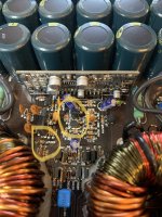
Q226 is located on the main board in front of the PS PWM card and pin 1 of Q226 connects to pin 3 of the PWM card through R268 and pin 3 of Q226 connects to a trace the goes up under one of the transformers through R266. D206 is connected to pin 5 of the PS PWM card.
D2 is located on the output driver card. I replaced it earlier when I was repairing the 3S Tech driver card because I found that it was shorted. I didn’t have any SMDs so I scabbed a through hole component in there to continue troubleshooting.
D2 is located on the output driver card. I replaced it earlier when I was repairing the 3S Tech driver card because I found that it was shorted. I didn’t have any SMDs so I scabbed a through hole component in there to continue troubleshooting.
Attachments
Last edited:
Of wow. I just realized my mistake. I misread the screen printing on the board. I get 0.6 ohms reading between D206 and D2. D206 connects to pin 11 of the PS PWM card.
Across D206 (in circuit) I get .591v forward reading and 2.099v reverse with meter in diode check mode.
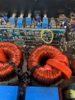
Just wanted to throw this out there but I would physically check all the small 47uh 5ohm green inductors. The last 3 clones I have found that the legs are busted off inside of the casing and the connection becomes intermittent. You have to physically desolder the part and tug both ends to make sure the leads don't come out.
Perry,
No. When I apply the remote the voltage on the cathode of both diodes jumps to 8 volts and then drifts down to about 2.3 volts and jumps back up to 8 volts and keeps cycling like that.
On the anode side I’m seeing a steady 0.174 volts on D206 and on D2 I’m seeing a steady 0.331 volts.
David
No. When I apply the remote the voltage on the cathode of both diodes jumps to 8 volts and then drifts down to about 2.3 volts and jumps back up to 8 volts and keeps cycling like that.
On the anode side I’m seeing a steady 0.174 volts on D206 and on D2 I’m seeing a steady 0.331 volts.
David
Do you read a short between the protect output pin of the driver board (connected to cathode of D2) and either of the adjacent pins?
No Perry. No direct short on either side.
With voltage applied I get 0.385 volts on the over current for bank A and bank B FETs. (Pins 7 and 15) With the black probe on the secondary center tap.
If I measure with black probe on negative rail I get -0.715 volts on pins 7 and 15.
If I cycle power it drops down to -0.500 volts and increases to -0.715 volts and holds there.
I put the rectifiers back into board with only one power supply mosfet per bank, so 4 total. I still have the output driver ICs shut down with jumpers. The amp powers up fine. Nothing heating up. I have voltages we’re they should be at the output driver board.
On pins 6 and 16 I’m getting 4.85 volts above negative rail. Over current input pins 7 and 15 is 0.0 volts above negative rail. Negative rail is -120 volts on pins 5 and 17.
I get 15 volts on pin 14. I get 11.95 volts on pin 4.
I’m getting +5 volts on pin 9 and -5 volts on pin 12.
I don’t know why this amp went squirrelly on me when I tried to use the low power, power supply jig. When I removed all 4 rectifiers and connected the jig it would go straight into protection and shut the power supply down before it even had a chance to start.
Anything else in need to check while I have the output ICs shut down?
I do not understand why this amp wouldn’t let me run the power supply with the rectifiers removed from the board. Most amps I’ve worked on will let you do that. Just wondering if I’m missing something or learning something.
I don't know. Did you ever find out why the amp was going into protect when neither external protection circuit was driving voltage to their diodes?
No. I went over every inch of the main board and the power supply PWM board and didn’t find anything. So I rolled the diced and reinstalled the rectifiers. And the amp powered up.
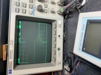
I have the 21844 jumpers removed and this is what the drive looks like on pin 1 and pin 21 of the driver card.
Scope settings are 5v/div 200us probe is 1x and grounded to the negative power terminal. 70 hertz signal is being fed into the amp.
Scope settings are 5v/div 200us probe is 1x and grounded to the negative power terminal. 70 hertz signal is being fed into the amp.
Attachments
- Home
- General Interest
- Car Audio
- 3-S Tech driver board muting transistor