I have one of the 3-S tech boards that’s been driving me crazy for a few hours.
Well, for starters, this DD amp was brought to me after someone else had already tried to fix it. I have spent considerable time checking and redoing all of the previous work. So now I only have myself to blame.
It looks like they did a partial repair on one bank of the high and low FETs and replaced the one IC on the driver board for that side.
The board is DWM3640NHV V30
The output section won’t oscillate. I replaced U1 and U2 and I also found that R21 was open and D2 was damaged. I went back with a 15v zenner for D2. Still I kept getting funky ohm readings across the cap on pin two (around 10k ohm range). Finally narrowed it down to the muting transistor Q6 is leaky. When I pulled the muting transistor my ohm reading on the cap on pin 2 went into the megohm region which is where it should be based on the other side. I carefully tested the transistor out of circuit and it tested leaky.
In Perry’s guide a 2SC3326 is mentioned as a suitable replacement but he had not confirmed it. Before a fire off an order for some I wanted to check if anyone else has confirmed that this is a good replacement.
Thanks Perry for your tutorial on these particular boards. Very helpful.
Thanks,
David
D2 is just a standard 1N4148 type diode.
What's the DC voltage on pin 2 of the 21844 with the black probe on the negative rail (shunt resistors or diode)?
What's the DC voltage on pin 2 of the 21844 with the black probe on the negative rail (shunt resistors or diode)?
Ok. So I found another one these driver boards laying around so I plucked a muting transistor from it and my ohm readings matched up to the other side. Around 1 megohm. I replaced the 15v zenner with a 1N4148 and got ready to see some magic.
Before the repair of the driver board the amp came up with a green LED but no oscillation in the output section.
Now when I power the amp up it tries to boot up for a split second and then flips on the red LED and stops producing rail voltage.
Before the repair of the driver board the amp came up with a green LED but no oscillation in the output section.
Now when I power the amp up it tries to boot up for a split second and then flips on the red LED and stops producing rail voltage.
Disable the two driver ICs by soldering a bridge from pin 2-3.
Then check the drive through to the driver IC, pin 1.
Then check the drive through to the driver IC, pin 1.
The reason the amp went into protection is because one of the FETs shorted on the opposite side that I was having trouble with. Just one FET. It shorted instantly. The source leg is connected to the rail. It was the last one in the bank close to the output driver card.
I had replaced all of the output FETs on both sides with brand new ones. Not sure what killed it.
The gate resistors all measure 47 ohms or within 0.2 ohms of that.
David
I had replaced all of the output FETs on both sides with brand new ones. Not sure what killed it.
The gate resistors all measure 47 ohms or within 0.2 ohms of that.
David
Last edited:
I prefer to see these amps troubleshot with low rail voltage. It's much safer.
Did you have to replace the 21844s on this board?
Did you have to replace the 21844s on this board?
When measuring most all voltages on the 21844s, you need to have the black probe on the negative rail?
Did you look at the drive signals on the output of the TL072, LM211 and the input of the 21844 with your scope?
Did you look at the drive signals on the output of the TL072, LM211 and the input of the 21844 with your scope?
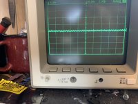
On the pin 1 of the 211 I have -5 volts DC and pin 7 I have a square wave swinging +\- 5 volts amplitude.
On the 072 on pin 1 I have what looks like a very small ekg noise around ground. Very low amplitude.
On pin 7 I have about -5 volts with EKG noise. Same pattern as pin 1.
No audio is being fed into the amp.
On the 072 on pin 1 I have what looks like a very small ekg noise around ground. Very low amplitude.
On pin 7 I have about -5 volts with EKG noise. Same pattern as pin 1.
No audio is being fed into the amp.
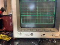
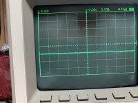
On the 21844 I have a square wave of +5 volts amplitude and back to ground.
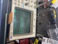
Scope was set a 50us to see the entire square wave.
Scope was set a 50us to see the entire square wave.
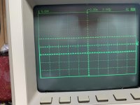
Drive a 50-100Hz signal into the amp and recheck the signal on the 3 ICs. You'll need to set the timebase to about 2ms.
The drive signal on pin 1 of the 21844 should swing from the negative rail to about 10v above the negative rail.
- Home
- General Interest
- Car Audio
- 3-S Tech driver board muting transistor