I don't like the talcum powder idea, I think it messes up the native stability of the drive.
You might have to give the platter a push at start up. I'm not sure why (or if) the motor will run backwards if overloaded. The only other fix would be to start the motor at a lower RPM to prevent torque overload and ramp up to 33RPM. This is what the Condor does.
You might have to give the platter a push at start up. I'm not sure why (or if) the motor will run backwards if overloaded. The only other fix would be to start the motor at a lower RPM to prevent torque overload and ramp up to 33RPM. This is what the Condor does.
I will go back through the setup to make sure I've got all the outputs balanced.I don't like the talcum powder idea, I think it messes up the native stability of the drive.
You might have to give the platter a push at start up. I'm not sure why (or if) the motor will run backwards if overloaded. The only other fix would be to start the motor at a lower RPM to prevent torque overload and ramp up to 33RPM. This is what the Condor does.
One odd thing is that it randomly started in re verse even without the belt on (i.e. no load). Bad motor?
Maybe. If one winding was bad, that could happen, but it will also be very noisy. Easy enough to substitute another motor if you have more than one.
I rebalanced the MA3D and tried again. So far it's working just fine. Likely I screwed up something in the first setup.
I am going to try another motor because I do have one. This one is a bit noisy.
I am going to try another motor because I do have one. This one is a bit noisy.
Depends on what job you are trying to do. Which motor would you be using it with? What are the motor requirements (voltage, power, frequency)?
Was thinking about any regular BLDC motor within the amp power range.
Would this amp work with the suggested bldc motor for this controller?
The amp you listed is configured for bridge output; this is common with class D amps as they are trying to maximize power output and bridged operation gives 4x the power output as single ended for the same supply voltage.
For low voltage motors like this project uses from Anaheim Automation, you cannot use bridged output amps, you must use a single ended amp, when connected directly (no step up xfmr) to the motor. There are not many class D amps that use a SE output topology. For line voltage motors, you can use a bridged output amp on the LV secondary side of a step up transformer and connect the HV primary side of the transformer to the motor as SE.
The amp should also be somewhat matched to the motor for voltage and power requirements. It doesn't make sense to use a 200W amp to drive a 12W motor. If you read the OP of this thread, it states that the design presented is for the particular motors, amps and sinewave generator, it is not a universal project that can be applied to whatever a user comes up with at a swap meet or from their parts bin. While elements of the design can be repurposed by the adventurous DIYer, I have neither the time nor the inclination to engineer solutions for everyone who takes that route.....in other words, you are on your own and do so at your own risk.
I went through the whole thread and am looking for a pulley for 0.25" shaft (BLWS motor) for use with VPI Classic that would support multiple drive belts. Is anyone offering one for sale?
Hello,
So, after a while with everything running great, I'm facing some issues.
Suddenly, the motor started to drift a lot, with constant variations of up to .5 rpm with a lot of heating coming from the motor.
I've always noticed some rpm drift compared to the stock vpi motor with the TDA amp from the previous build, but I assumed it was because of the different configuration as the BLDC motor is a DC motor and the stock one is AC.
The wake up call came today, when the motor "died" while running, like an airplane stalling... and then I touched the pod to find it really hot.
What can I do?
The last time you had similar problems (April) it was one of the TDA3123 amps; I would look at that again. The speed should drift very little when the system is working correctly.
Yeah, I'll open the unit and check every voltage again... But isn't it odd to have another faulty tda ic? The setup works fine while the motor is cool, I've just checked... The problems occurs after the pod gets hot.
Can you measure the temp of the motor? Better yet, can you measure the current consumption going into the amplifier PCB?
The motor should not get much hotter than 50°C at 12W. If the motor is drawing too much power, it will get hotter and the amps will be stressed.
The motor should not get much hotter than 50°C at 12W. If the motor is drawing too much power, it will get hotter and the amps will be stressed.
Bill,
The measurements are attached.
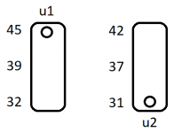
The u1 is showing odd values again for pin 19... Something on the circuit could be damaging the chips?
I've run the motor for 90min, without the platter, and the temperature was 55 C (infrared thermometer with EMIT setting to 0,1). Yesterday the motor was on for around 6h when it started to fail.
The measurements are attached.
The u1 is showing odd values again for pin 19... Something on the circuit could be damaging the chips?
I've run the motor for 90min, without the platter, and the temperature was 55 C (infrared thermometer with EMIT setting to 0,1). Yesterday the motor was on for around 6h when it started to fail.
Attachments
Last edited:
U1 does not look right; everything else seems to be OK. If the chips are in sockets, you could try replacing U1.
Does U1 or U2 get hot when it has been operating for some time?
Does U1 or U2 get hot when it has been operating for some time?
Was thinking about any regular BLDC motor within the amp power range.
Would this amp work with the suggested bldc motor for this controller?
TPA3123 Stereo boards are available and cheap from the usual outlets (Aliexpress, Ebay...). These are SE output.
Bill,
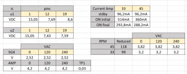
here are the temperature (Celsius) on the ics after 30 min of operation, with the platter
I'll proceed with the ic replacement, but it will take a while... can't find it here in Brazil so I'll have to order from mouser.
Is there any other component that I should consider replacing? Two ics having issues on the same pin does sound strange to me.
I measured the VDC on the output terminal block and the readings are 8.2 to pin 0, 7.69 pin 120 and 7.59 pin 240.
How can the VAC reading be roughly the same for all three pins (3.2) and be different when measuring VDC?
Attachments
The VDC reading will be the filtered average of output and should be VCC/2. The VAC reading will be affected by the changing duty cycle of the output.
The temps look a bit high for the ICs. If there is an imbalance of the VDC output, they will draw excessive current which may account for the increase. They make small heat sinks designed for 24 (or 40) pin DIP ICs that could be glued to the tops of the TPA3123 chips that may help them run cooler.
The temps look a bit high for the ICs. If there is an imbalance of the VDC output, they will draw excessive current which may account for the increase. They make small heat sinks designed for 24 (or 40) pin DIP ICs that could be glued to the tops of the TPA3123 chips that may help them run cooler.
Also, you should not connect/disconnect the output to/from the motor while powered up; the voltage spikes into an inductive load could be causing the failure.
Ok, I'll order the heatsinks.
I never plug or unplug anything while the unit is on.
I believe the parts will take up to a month to arrive, so I'll get back to you then.
Thanks!
I never plug or unplug anything while the unit is on.
I believe the parts will take up to a month to arrive, so I'll get back to you then.
Thanks!
Bill,
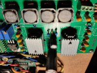
I´ve managed to get the parts and changed them. The DC voltages are back to normal and I´ve installed heatsinks on the ICs. I used some to-220 heatsinks that I had laying around, 'glued' on the top with just a layer of thermal paste. I´ll monitor the temp from time to time.
The voltage readings for the three output pins are all around 7.59 VDC.
Also, can you tell me how much current goes through each pushbutton on the SG4? I´m thinking about putting together some sort of IR remote to adjust the RPM from the couch, using arduino & optocoupler.
On another topic (but related to electronics): I´ve stumbled uppon this kickstarter campaign of a pocket multimeter and oscilloscope that I believe could be useful for some of us.
Ps.: I have no idea why the picture is flipped, the original isn´t.
Pokit PRO | All-in-one multimeter, oscilloscope and logger by Pokit Innovations — Kickstarter
Attachments
Last edited:
- Home
- Source & Line
- Analogue Source
- 3 Phase Class D amp for DIY BLDC motor Drive