Hi, if you've ever taken apart a commercial amplifier designed for use with 3.5mm jacks from a computer or phone then you'll have noticed that most of them include a combination of capacitors and resistors right at the input jack. The values are usually a few 100 pF and a few kohm at most.
But looking in the datasheets for many chip amps such as LM386 and TDA2050 etc most of them are just general application sheets and don't really show you how to go the extra mile with input jack RF filtering.
What sorts of filtering do you guys use when designing a 3.5mm jack into a chip amp build? I know how to calculate RC cut off values but don't know about where to place them exactly, before or after the volume pot? before or after the DC blocking capacitor?
I'm mainly just looking for some guidance on the subject of input jack RF filtering since the datasheets don't appear to mention it.
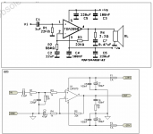
For example the top screencap is from the TDA2050 datasheet whilst the bottom one is from a picture I found on google images, its clear the extra components on the bottom one are for keeping out unwanted noise but I can't find any articles or threads discussing them.
Thanks.
But looking in the datasheets for many chip amps such as LM386 and TDA2050 etc most of them are just general application sheets and don't really show you how to go the extra mile with input jack RF filtering.
What sorts of filtering do you guys use when designing a 3.5mm jack into a chip amp build? I know how to calculate RC cut off values but don't know about where to place them exactly, before or after the volume pot? before or after the DC blocking capacitor?
I'm mainly just looking for some guidance on the subject of input jack RF filtering since the datasheets don't appear to mention it.
For example the top screencap is from the TDA2050 datasheet whilst the bottom one is from a picture I found on google images, its clear the extra components on the bottom one are for keeping out unwanted noise but I can't find any articles or threads discussing them.
Thanks.
Attachments
Last edited:
Wow, good question! Subscribing to this discussion.
Sent from my iPhone using Tapatalk
Thanks, hopefully we'll get some answers. I did some forum searching but surprisingly little came up that was easy to understand with illustrations.
I think this subject definitely deserves some discussion as its probably one of those things that can really make an amplifier sound great.
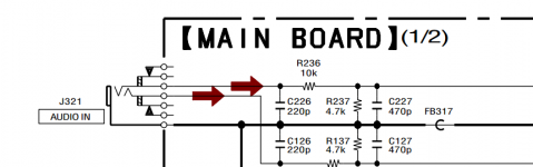
In the meantime I came across the service manual for my Sony hifi, here is the 3.5mm aux input jack and its associated RF filtering. There is also an additional resistive divider further up before it enters the volume control IC and even more RC networks once it exits that.
If this is one of those things that sets apart the amateur designs to the commercial ones then no wonder its such a closely guarded secret 😀
Attachments
Last edited:
You have not been reading any of my recommendations to always fit passive filtering to the input of all your audio gear.
A High Pass filter to block DC from damaging subsequent equipment and a Low Pass filter to attenuate the RF that contaminates our homes.
These two filters also define the passband of the equipment and help to ensure that the equipment can properly process the signals that pass into the equipment.
A High Pass filter to block DC from damaging subsequent equipment and a Low Pass filter to attenuate the RF that contaminates our homes.
These two filters also define the passband of the equipment and help to ensure that the equipment can properly process the signals that pass into the equipment.
What sorts of filtering do you guys use when designing a 3.5mm jack into a chip amp build?
Input transformers because they provide the best filtering - from both common-mode and normal-mode noise. Input RC filters only provide normal-mode filtering.
That's just what I needed, thanks!
So the input DC blocking cap is the high pass filter preventing DC and the low pass filter is usually the small 100-400pF capacitor and series resistor combo? I have a small ferrite bead in series with each channel but I guess they could make it worse with no low pass filter to shunt the RF to ground.You have not been reading any of my recommendations to always fit passive filtering to the input of all your audio gear.
A High Pass filter to block DC from damaging subsequent equipment and a Low Pass filter to attenuate the RF that contaminates our homes.
These two filters also define the passband of the equipment and help to ensure that the equipment can properly process the signals that pass into the equipment.
Also where abouts have I missed one of your recommendations?
Input transformers because they provide the best filtering - from both common-mode and normal-mode noise. Input RC filters only provide normal-mode filtering.
I see, so is this what these things are designed to do Miniature Audio Matching Transformer 200mW | Maplin and 1+1 : 1+1 Audio Input Transformer 600R | Maplin
By being lossy above a certain frequency they can "choke" out any potential RF?
In my posts. I have given this recommendation dozens of times, I doubt it has reached a hundred yet, but I have to keep repeating it because our Members won't read......................
Also where abouts have I missed one of your recommendations?...........
I see, so is this what these things are designed to do Miniature Audio Matching Transformer 200mW | Maplin and 1+1 : 1+1 Audio Input Transformer 600R | Maplin
Details look to be rather sparse so I hesitate to agree with your sentence above. The impedances do look to be rather low for use as input transformers, the first definitely looks to be an inter-stage trafo, the second might be suitable for microphone inputs.
By being lossy above a certain frequency they can "choke" out any potential RF?
There's rather more to transformer filtering than merely their leakage inductance (which is what I take you to be meaning by '"lossy above a certain frequency"). But yes its one aspect of differential mode RF filtering.
In my posts. I have given this recommendation dozens of times, I doubt it has reached a hundred yet, but I have to keep repeating it because our Members won't read.
My apologies, I did do some searching before but couldn't really find much that looked relevant among the countless unrelated posts that turned up.
I would like to read some of these though so which threads are they located in?
Details look to be rather sparse so I hesitate to agree with your sentence above. The impedances do look to be rather low for use as input transformers, the first definitely looks to be an inter-stage trafo, the second might be suitable for microphone inputs.
There's rather more to transformer filtering than merely their leakage inductance (which is what I take you to be meaning by '"lossy above a certain frequency"). But yes its one aspect of differential mode RF filtering.
Which input filter transformer part numbers have you used in the past? I don't want to end up buying something that won't work.
The input impedance of these chip amps seem to be around 30kohm and the output impedance of computers/tablets/phones must be low as they can all drive headphones directly, so I'm guessing it needs to have a high impedance primary and low impedance secondary coil.
Which input filter transformer part numbers have you used in the past? I don't want to end up buying something that won't work.
I've not been able to find suitable transformers off the shelf, so I wound my own. Ferrite cores are cheap and readily available, EP19 is probably the smallest I've used, PQ2020 also for slightly larger ones.
The input impedance of these chip amps seem to be around 30kohm and the output impedance of computers/tablets/phones must be low as they can all drive headphones directly, so I'm guessing it needs to have a high impedance primary and low impedance secondary coil.
From my own experiments smartphones sound best when they're driving high impedances (above 100kohm). Chipamp input impedance can be chosen within certain bounds, the ICs themselves (at least LM38xx and TDA20x0 types) don't determine it. The turns ratio is a function of how much gain you give the amp and the maximum output swing, given phones are generally limited to 1VRMS.
I know how to calculate RC cut off values but don't know about where to place them exactly, before or after the volume pot? before or after the DC blocking capacitor?
RC filters should not be placed "after" the volume control as it will be a variable filter (yes think about that for a moment) with possibly audible results. I know some manufacturers have done so in the past but it is not right. They should be before the potentiometer.
Normally there is little DC at the input so first RC filter, then coupling cap, then potentiometer. Sometime the coupling cap is omitted and it is then placed after the wiper of the potentiometer. This might work but any significant DC at the input will result in a scratching sound when adjusting volume. I would call it wrong application.
Last edited:
I've not been able to find suitable transformers off the shelf, so I wound my own. Ferrite cores are cheap and readily available, EP19 is probably the smallest I've used, PQ2020 also for slightly larger ones.
From my own experiments smartphones sound best when they're driving high impedances (above 100kohm). Chipamp input impedance can be chosen within certain bounds, the ICs themselves (at least LM38xx and TDA20x0 types) don't determine it. The turns ratio is a function of how much gain you give the amp and the maximum output swing, given phones are generally limited to 1VRMS.
Thanks! I've got a few odd cores laying around so I'll give them a try.
So you think the dual 10k pot I have right now might be a little on the low side for the average computer based device?
RC filters should not be placed "after" the volume control as it will be a variable filter (yes think about that for a moment) with possibly audible results. I know some manufacturers have done so in the past but it is not right. They should be before the potentiometer.
Normally there is little DC at the input so first RC filter, then coupling cap, then potentiometer. Sometime the coupling cap is omitted and it is then placed after the wiper of the potentiometer. This might work but any significant DC at the input will result in a scratching sound when adjusting volume. I would call it wrong application.
That's knowledge right there! So best practice is to place the RC low pass network right after the input jack?
Also that might explain why the LA4705 amp I built a few years ago scratches when adjusting the pot, its DC blocking capacitor needs to go at the chips input after the wiper as the chip doesn't like paths to ground on its input (causes the current draw to shoot up and eventually hit the internal limit).
What would be the best course of action here if the DC blocking capacitor needs to be placed between the wiper and chip input in order to keep the chip happy?
Yes after the input jack as that is where the action is.
If the amplifier is unhappy when directly hooked up to the wiper of the potentiometer then a very high ohmic resistor like 470 kOhm should be connected from wiper to GND (in case the wiper does not make contact, think a moment about that) and the coupling cap from wiper to the input of the amplifier. The RC filter can still be at the input jack in this case.
If the amplifier is unhappy when directly hooked up to the wiper of the potentiometer then a very high ohmic resistor like 470 kOhm should be connected from wiper to GND (in case the wiper does not make contact, think a moment about that) and the coupling cap from wiper to the input of the amplifier. The RC filter can still be at the input jack in this case.
Last edited:
Yes after the input jack as that is where the action is.
If the amplifier is unhappy when directly hooked up to the wiper of the potentiometer then a very high ohmic resistor like 470 kOhm should be connected from wiper to GND (in case the wiper does not make contact, think a moment about that) and the coupling cap from wiper to the input of the amplifier. The RC filter can still be at the input jack in this case.
Thanks again, so if the wiper suddenly floats because of poor contact it could potentially cause the chips input pin to float at unknown voltages? The 470kohm resistor just pulls the wiper and other end of the DC blocking capacitor to 0v in the event of that happening?
The first drawing shows what I currently have in place whilst the second is what I plan on doing with the advice of this thread. Are input ferrite beads still a good idea or shall I just take them out? I can see a potential low Q tank being set up with the bead and 220pF capacitor.
Attachments
Last edited:
Aha deleted my post as I only saw one picture with the R missing in the RC filter 😉 Maybe the R from wiper to GND is exaggerated in this case but it won't hurt. I guess you can omit them. The corrected schematic looks OK.
Make sure to have film caps for C1 and C2.
* Question: what chip is this and do you know what its input impedance is ? 10 kOhm is quite low for volume control but OK if you sources can drive that. Any decent source should not fear 10 kOhm except tube buffers/preamps etc.
* I see you have predefined the use of a 3.5 mm jack. I have a strong opinion of those as they always seem to scratch and become defective especially the most used Thro A Wei type from the famous Chi Po factory in China. You know, that black ones that you will replace tens of times in your life. RCA/cinch are way better as they will never scratch. Up to you. Even a 3.5 mm connector at one side and RCA's at the other is better than 3.5 mm jack to 3.5 mm jack cables.
* I am not so sure of the beads. If they are the simple beads (wire through bead) then it's OK. If they are real coils then it might not be optimal.
Last edited:
Aha deleted my post as I only saw one picture with the R missing in the RC filter 😉 Maybe the R from wiper to GND is exaggerated in this case but it won't hurt. The corrected schematic looks OK.
Make sure to have film caps for C1 and C2.
* Question: what chip is this and do you know what its input impedance is ? 10 kOhm is quite low for volume control but OK if you sources can drive that. Any decent source should not fear 10 kOhm except tube buffers/preamps etc.
The second pic was an edit, sorry about that.
Its an LA4705 pulled out of some old junk a while back (wish I had kept the original board now) but the datasheet says "input resistance - 30kohm", that refers to the input impedance right? However if I measure between the input pin and ground with my multimeter it reads closer to 80k for some reason...
Datasheet HTTP 301 This page has been moved
I mostly just drive this thing with my laptop and phone so the 10k input impedance should be ok I guess, but my next amp will use a higher resistance pot so it can be used with other sources.
This build is mostly about the learning experience before moving onto bigger and better amps, I've only recently got back into electronics so that explains my rusty knowledge.
Edit: Here is the jack in question http://www.maplin.co.uk/p/35mm-pcb-mounting-stereo-socket-jm20w
It seems ok now *touch wood* but I mainly selected it for compatibility with my computer and phone.
http://www.maplin.co.uk/p/35mm-pcb-mounting-stereo-socket-jm20w
Last edited:
The ferrite bead adds impedance to what line/s are pushing through it.
The impedance that is added is not linear, so you have to be careful you don't add distortion to your wanted signal.
To avoid adding impedance to your audio signals, you pass both the Flow and Return through the same hole in the bead. This way the inductance does not see a net current flow and thus adds no impedance to the wanted audio signal.
But, if there is any common mode interference on BOTH the Flow and Return lines, then the bead inductance does add impedance to that interference current.
Now that bead is on the outside of your enclosure.
Add a capacitor from Cold to enclosure to shunt some of the common mode interference to enclosure and from Hot to enclosure to shunt some of the common mode interference to the enclosure. So far you have only attenuated the common mode interference.
I have never implemented this bead + common mode interference suppression, but it is described in H.Ott and I think I have interpreted his instruction correctly.
Add a small pF NPO capacitor to the input socket from Hot to Cold to shunt some differential interference, before it gets on to the internal cabling. I use 47pF
When you arrive at the amplifier PCB, add on some RF attenuation using the series resistance before this point and another NPO capacitor to shunt differential mode interference from Hot to Cold.
You have effectively added 4 filters to attenuate RF before it gets into the amplifier. And some of it will be after the vol pot. That can't be helped. You just use some value adjustments to make sure you don't attenuate the wanted audio signal. I aim for 160kHz to 240kHz here. eg 1k0 & 680pF.
Last edited:
Lower impedance volume control has its benefits but normally one would choose a 25 kOhm type when the amplifier is 30 kOhm. Considering you drive this amp with a phone I would change it to a 25 kOhm log potentiometer. You can't measure input impedance of an amplifier with a DMM the way you have done.
I knew you would ask so here it is. My top 5 of worst connectors of all time:
1. micro USB. Sometimes already defective after plugging your phone in 5 times
2. 3.5 mm jack. Scratching and refusing contact through decades.
3. Apple's 30 pin connector as found on Iphone 4 and older types. Never a dull moment.
4. HiRose U.FL connectors. Always the 30 mating times type is chosen. Microscope needed when connecting.
5. HDMI. No retention system and when you hot plug either the TV or the other device breaks down. Nice sparks though when plugging in in the dark. Only hot pluggable connector in the world that better not is hot plugged.
It was a close call between HDMI and RJ11/RJ45 but the latter work OK when treated kindly.
Our grandchildren will see all those in a museum and think of the misery gramps went through working with these while they still are using your CD player and those shiny disks with old fashioned music.
Last edited:
I used the word "attenuation" in 927 posts.My apologies, I did do some searching before but couldn't really find much that looked relevant among the countless unrelated posts that turned up.
I would like to read some of these though so which threads are they located in?
.............
I used the words "low pass" in over 900 posts.
One of the recent was just 7days ago and is the same topic as today.
http://www.diyaudio.com/forums/part...es-inductance-insertion-loss.html#post4948955
- Status
- Not open for further replies.
- Home
- Amplifiers
- Chip Amps
- 3.5mm input jack RF bypassing and filtering