No, connecting the chassis AND input RCA GND to PE won't make things better. It is a UK habit, yes. It will cause more problems than it solves.
A metal chassis should be connected to PE directly but not signal GND. It is better to lift that in a safe way. Tens of posts have discussed this so I won't repeat. I have a second hobby as ground loop solver and any UK made source device that has audio GND and PE connected is the subject of immediate surgery when it passes my front door. The patients always thank me later for it as it cures hum illness.
A metal chassis should be connected to PE directly but not signal GND. It is better to lift that in a safe way. Tens of posts have discussed this so I won't repeat. I have a second hobby as ground loop solver and any UK made source device that has audio GND and PE connected is the subject of immediate surgery when it passes my front door. The patients always thank me later for it as it cures hum illness.
Last edited:
No connecting the chassis AND input RCA GND to PE won't make things better. It is a UK habit, yes. It will cause more problems than it solves.
Not quite what I was meaning. I was meaning that the star point for all audio GNDs is best located at the RCA inputs, then one of the wires from that star goes by as short a length as possible to chassis. If you prefer a GND lift then this short wire can be replaced by a resistor or inductor or bridge rectifier or whatever takes your fancy.
Far from just being a UK habit, it has also been recommended by Jan Didden who's from across the Channel.
Exceptions confirm the rule 😀 There is not a single regulation that tells us to connect audio GND to PE. It mostly is not done. PE should be connected to chassis for safety like in the UK and elsewhere.
If it would not be a UK habit I would not have encountered almost exclusively british made equipment that has this nasty habit. With habit I mean a fancy 0 Ohm between audio GND and PE and a free ground loop as a gift.
If it would not be a UK habit I would not have encountered almost exclusively british made equipment that has this nasty habit. With habit I mean a fancy 0 Ohm between audio GND and PE and a free ground loop as a gift.
Last edited:
No, connecting the chassis AND input RCA GND to PE won't make things better. It is a UK habit, yes. It will cause more problems than it solves.
A metal chassis should be connected to PE directly but not signal GND. It is better to lift that in a safe way. Tens of posts have discussed this so I won't repeat. I have a second hobby as ground loop solver and any UK made source device that has audio GND and PE connected is the subject of immediate surgery when it passes my front door. The patients always thank me later for it as it cures hum illness.
Not quite what I was meaning. I was meaning that the star point for all audio GNDs is best located at the RCA inputs, then one of the wires from that star goes by as short a length as possible to chassis. If you prefer a GND lift then this short wire can be replaced by a resistor or inductor or bridge rectifier or whatever takes your fancy.
Far from just being a UK habit, it has also been recommended by Jan Didden who's from across the Channel.
Its all 12v battery powered so no mains earthing here. So its best to have two separate star points, one at the input jack and one for the power section and then just jumper them over with a single link? The signal and power sections do have their own separate zones but I guess there are some very small runs where both input channels share the same return back to the input jack.
Maybe about 2cm in total between the input jack and potentiometer, ie both gangs of the dual pot share a single small (less than 1cm) return conductor back to the input jack.
Then after that its just a single jumper between the input grounds and power ground, but my understanding is that no audio input signal current should travel down this link.
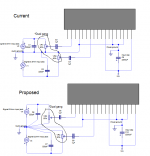
Should I separately star the input grounds or is it just not really worth the modifications at sub centimeter lengths? I drew a schematic to explain it better, excuse the lowish resolution but I did it on a laptop. Second pic is from the datasheet.
Attachments
But there is a rule that all exposed conductive parts should be connected to the protected Chassis.There is not a single regulation that tells us to connect audio GND to PE.
So the outcome for all ClassI products is the Chassis is directly connected to PE. And all the screwheads and RCA barrels and Speaker terminals and metal adjustment knobs/shafts that have any exposed metal and etc... are connected to that Chassis.
Give the input signal wires a TWO WIRE close coupled connection. Same for the output signal. Same for the Power supply(signal).Its all 12v battery powered so no mains earthing here. So its best to have two separate star points, one at the input jack and one for the power section and then just jumper them over with a single link? The signal and power sections do have their own separate zones but I guess there are some very small runs where both input channels share the same return back to the input jack.
Maybe about 2cm in total between the input jack and potentiometer, ie both gangs of the dual pot share a single small (less than 1cm) return conductor back to the input jack.
Then after that its just a single jumper between the input grounds and power ground, but my understanding is that no audio input signal current should travel down this link.
Should I separately star the input grounds or is it just not really worth the modifications at sub centimeter lengths? I drew a schematic to explain it better, excuse the lowish resolution but I did it on a laptop. Second pic is from the datasheet.
Give every intermodule connection it's own TWO WIRE (Flow and Return) connection.
Then look to see if any voltage reference is missing. Add that where necessary.
But there is a rule that all exposed conductive parts should be connected to the protected Chassis.
So the outcome for all ClassI products is the Chassis is directly connected to PE. And all the screwheads and RCA barrels and Speaker terminals and metal adjustment knobs/shafts that have any exposed metal and etc... are connected to that Chassis.
That depends on how you look at it (and where you live). One is eager to exaggerate to the max in some areas. That the metal chassis should be connected to PE is no issue. That is the same everywhere where a human life is valued. Here we don't connect audio GND to PE except in power amplifiers. Measures are taken to take care of possible risks and to reduce as much as possible. Admitted, these are not so easy for most DIYers. Simply connecting everything including audio GND to PE does not cut the cake and it is the way of least resistance. Sorry. An audio device should function properly and when all devices one has have audio GND connected to PE the equipment does not function properly. We will debate this for years to come, I know 🙂
BFA is an example of going too far 😀
Last edited:
Its all 12v battery powered so no mains earthing here.
With no connection to earth and no mains transformer, the common-mode noise issues won't be mains-related which is a relief 😀 But there will still be potential CM noise issues related to the cables (input, speaker) acting as antennas. This puts the frequency of interest of the CM noise into a much higher band (where the cables are effective antennas) than with a mains connected system, meaning in theory its easier to filter it. However I have no experience of designing with battery powered amps myself so no practical tips to offer.
So its best to have two separate star points, one at the input jack and one for the power section and then just jumper them over with a single link? The signal and power sections do have their own separate zones but I guess there are some very small runs where both input channels share the same return back to the input jack.
I'd say suck it and see.
Should I separately star the input grounds or is it just not really worth the modifications at sub centimeter lengths? I drew a schematic to explain it better, excuse the lowish resolution but I did it on a laptop. Second pic is from the datasheet.
Not worth the bother in a battery powered system.
Here we don't connect audio GND to PE except in power amplifiers.
Had it by any small sliver of a chance escaped your attention that this is what the OP is working on? 😀
Save
Mains fed power amplifiers that is. I have never seen a PE connection on batteries.
Logic, a difficult item.
Logic, a difficult item.
Last edited:
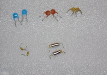
Alrighty then so I've had a good rummage around in the capacitor box and came across these types in the values I need, which would be the better choice for the application of RC input filtering?
I know that AndrewT recommended NPO disc capacitors for stability but I can't find any with that printed on them in the box. Are any of these good enough or will I face distortion/oscillations using them?
The blue ones are rated for 1kV and came out of an old SMPS, the orange ceramic ones are the usual kind, the yellowy ones came out of some old RF module IIRC, the tiny axial ones out of an old TV, and lastly the silver ones look like low cost foil types from goodness knows what.
There must be pros and cons to each type I guess.
Attachments
The styroflex are best. Debatable but they heave the least impact on sound quality. However I would order some brand new film caps.
All the others are ceramic caps of the kind you don't want to use in the signal path.
All the others are ceramic caps of the kind you don't want to use in the signal path.
The styroflex are best. Debatable but they heave the least impact on sound quality. However I would order some brand new film caps.
All the others are ceramic caps of the kind you don't want to use in the signal path.
What about these? 278 Pcs 30 Values Polyester Film Capacitor Assorted Assortment Kit 470pf - 470nf | eBay
Or these http://www.maplin.co.uk/p/wima-polypropylene-film-and-foil-100v-470pf-capacitor-n02cn
Probably a bunch of production rejects but should be ok for low voltage audio?
Last edited:
Which WIMA series is that? MKP10, MKP4?
Sent from my iPhone using Tapatalk
I am not the seller but AFAIK they're FKP2 so fine for the job. MKP or FKP, both are better than any of the caps OP already has.
AFAIK they're FKP2 so fine for the job.
Thank you Jean Paul.
Sent from my iPhone using Tapatalk
- Status
- Not open for further replies.
- Home
- Amplifiers
- Chip Amps
- 3.5mm input jack RF bypassing and filtering