I used the word "attenuation" in 927 posts.
I used the words "low pass" in over 900 posts.
One of the recent was just 7days ago and is the same topic as today.
Let me guess.... you live in an area with lots of high power transmitters ?!
Last edited:
cellphone, wireless burglar alarm, WiFi, fluorescent lamps, smps and etc..... infesting your home is probably a lot worse than a 100kW transmitter 10miles (16km) away
Recently had some nice experiences with LED bulbs. Apparently the SMPS in some of those is not our friend in audio. In fact I don't have many friends amongst SMPS. I think we should send them all back to where they came from.
Last edited:
cheaper to throw them in the bin and just generate more CO2 using coal fired power stations.
Nuclear has the power to save the planet, but we still harp on about the potential dangers.
Just a week or so ago someone here posted the number of deaths from electricity caused fires in the USA (was it 400/annum?).
How many are electrocuted each year?
Now multiply them up for world wide numbers and compare to how many have died from nuclear accidents.
RF filtering.... so, I run a bunch of vintage gear, and one of the biggest problems I run into is when an iPhone is plugged in and playing. Whenever it sends and receives over cellular, I get interference. I have to put it in Airplane mode, and then of course I can't play from Pandora. This only happens with some receivers. And I haven't yet tracked it down as to whether it's based on the receiver or the cable or what. Would some kind of RF filtering circuit protect against this?
Charles.
Charles.
Coupling a 2W transceiver to an analog device does that. Hard to get rid of. Many use Bluetooth or wireless to overcome it. You will need a separate Bluetooth or wireless receiver for that. Wireless is (arguably) better for audio. The infamous Rocki Play was designed for this. Many complaints though. When the owner knows how to configure it works better than Bluetooth devices. It has its own Li Ion battery that gives many hours of listening. I stopped trying out such devices but I am sure there are more comparable devices. Airmobi Ireceiver can be found in the US.
Last edited:
The ferrite bead adds impedance to what line/s are pushing through it.
The impedance that is added is not linear, so you have to be careful you don't add distortion to your wanted signal.
To avoid adding impedance to your audio signals, you pass both the Flow and Return through the same hole in the bead. This way the inductance does not see a net current flow and thus adds no impedance to the wanted audio signal.
But, if there is any common mode interference on BOTH the Flow and Return lines, then the bead inductance does add impedance to that interference current.
Now that bead is on the outside of your enclosure.
Add a capacitor from Cold to enclosure to shunt some of the common mode interference to enclosure and from Hot to enclosure to shunt some of the common mode interference to the enclosure. So far you have only attenuated the common mode interference.
I have never implemented this bead + common mode interference suppression, but it is described in H.Ott and I think I have interpreted his instruction correctly.
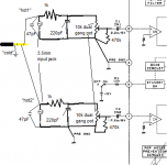
Add a small pF NPO capacitor to the input socket from Hot to Cold to shunt some differential interference, before it gets on to the internal cabling. I use 47pF
When you arrive at the amplifier PCB, add on some RF attenuation using the series resistance before this point and another NPO capacitor to shunt differential mode interference from Hot to Cold.
You have effectively added 4 filters to attenuate RF before it gets into the amplifier. And some of it will be after the vol pot. That can't be helped. You just use some value adjustments to make sure you don't attenuate the wanted audio signal. I aim for 160kHz to 240kHz here. eg 1k0 & 680pF.
Thanks, as well as the RC low pass filter I'll add the smaller capacitor across input jack too. I think I'll just remove the series ferrite beads since they were pulled out of some old junk and I have no idea of their true characteristics.
Does Hot and Cold refer to one of the incoming audio channels and ground at the jack? (see attached paint drawing).
Lower impedance volume control has its benefits but normally one would choose a 25 kOhm type when the amplifier is 30 kOhm. Considering you drive this amp with a phone I would change it to a 25 kOhm log potentiometer. You can't measure input impedance of an amplifier with a DMM the way you have done.
I knew you would ask so here it is. My top 5 of worst connectors of all time:
1. micro USB. Sometimes already defective after plugging your phone in 5 times
2. 3.5 mm jack. Scratching and refusing contact through decades.
3. Apple's 30 pin connector as found on Iphone 4 and older types. Never a dull moment.
4. HiRose U.FL connectors. Always the 30 mating times type is chosen. Microscope needed when connecting.
5. HDMI. No retention system and when you hot plug either the TV or the other device breaks down. Nice sparks though when plugging in in the dark. Only hot pluggable connector in the world that better not is hot plugged.
It was a close call between HDMI and RJ11/RJ45 but the latter work OK when treated kindly.
Our grandchildren will see all those in a museum and think of the misery gramps went through working with these while they still are using your CD player and those shiny disks with old fashioned music.
Add apple lighting connectors to that list, they basically include DRM and don't normally last more than 12 months in general use imo.
I used the word "attenuation" in 927 posts.
I used the words "low pass" in over 900 posts.
One of the recent was just 7days ago and is the same topic as today.
http://www.diyaudio.com/forums/part...es-inductance-insertion-loss.html#post4948955
Thanks, I'm like a sponge at the moment so i'll get reading. It appears that the google search option is better than the native forum search engine.
cellphone, wireless burglar alarm, WiFi, fluorescent lamps, smps and etc..... infesting your home is probably a lot worse than a 100kW transmitter 10miles (16km) away
Recently had some nice experiences with LED bulbs. Apparently the SMPS in some of those is not our friend in audio. In fact I don't have many friends amongst SMPS. I think we should send them all back to where they came from.
You guys would hate it here, lots of houses in close proximity and our 3rd floor loft room has dimmable GU10 LED's on a regular dimmer who's interference can be heard on a radio for quite some distance.
Attachments
Last edited:
Please elaborate with regards to the lightning connector. I have not yet experienced defects but had countless ones with the 30 pin thing. DRM ? I should know that but I would not know how to put music on my Iphone except when buying it from Apple. So I never bothered to play my own music on it.
Hot and Cold are other terms for Flow and Return....................
Does Hot and Cold refer to one of the incoming audio channels and ground at the jack? (see attached paint drawing).
..................
I try to avoid using the ground word.
It causes too much confusion and part of that confusion is that most grounds are not. They are the Return routes for the Signal Flow.
A signal connection must contain two wires. Signal Flow and Signal Return. It does not matter that you are talking about a an RF aerial coaxial, or a line level, or a speaker or a mains power cable. Every Flow from a SOURCE must RETURN to that Source. There are no exceptions.
A long paragraph that covers 99% of the wiring and connections and traces and cables and not a sngle mention of the word ground !
Your diagram in post28 shows multiple connections to an "E" symbol. I read that as Chassis that is connected directly to the PE wire in the mains cable. Do not make more than ONE connection from Main Audio Ground (MAG) to Chassis. That single connection must be capable of passing Main's Fault current approaching and even exceeding a kA.
The Cold connection at the incoming cable shows a three bar symbol indicating an audio ground. That is actually the signal return wire and to to the signal input. See first para.
Last edited:
Please elaborate with regards to the lightning connector. I have not yet experienced defects but had countless ones with the 30 pin thing. DRM ? I should know that but I would not know how to put music on my Iphone except when buying it from Apple. So I never bothered to play my own music on it.
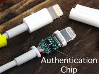
The lightning cables have a small ID chip built into the end of the phone connector which apple checks against a database when you plug it in, if it doesn't like it then it will refuse to charge using that cable. And that chip area protrudes out of the device just enough that the cable becomes a major weak point because of all the bending and twisting it has to endure, I've just had a replacement split open within 6 months with careful use.
Now that apple have gotten rid of other ports such as 3.5mm jacks it means everything goes through that lightning connector.


Also what ever happened to port covers? lighting connectors are so cavernous that lint from my pocket always gets jammed up inside it needing tweezers to remove.
Attachments
Ah yes I knew this. I thought you meant DRM for music as I was not aware this is also called DRM. I got some free Lightning cables and even thoughg some cause a message they still charge my iPhone. Never experienced a cable not charging it (till now). As said also no defective ones yet. Nothing is perfect but compared to the 30 pin and micro USB the Lightning connector is heaven.
Hot and Cold are other terms for Flow and Return.
I try to avoid using the ground word.
It causes too much confusion and part of that confusion is that most grounds are not. They are the Return routes for the Signal Flow.
A signal connection must contain two wires. Signal Flow and Signal Return. It does not matter that you are talking about a an RF aerial coaxial, or a line level, or a speaker or a mains power cable. Every Flow from a SOURCE must RETURN to that Source. There are no exceptions.
A long paragraph that covers 99% of the wiring and connections and traces and cables and not a sngle mention of the word ground !
Thanks for the clarification, for some reason I was getting confused and thinking you were referring to live and neutral connections and by connecting capacitors to a metal enclosure it would have an actual true earth reference.
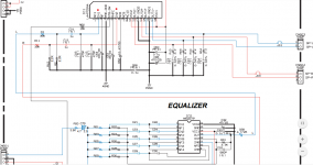
Well after much searching and clicking on dodgy Chinese websites I managed to come across some actual commercial schematics featuring the LM4705 chip amp.
However in the first screencap the input filtering sections appear to be in the wrong order and the DC blocking capacitor is between the resistor and small capacitor. Then I came across a different one in the second image that had another weird arrangement.
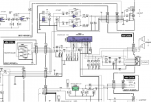
Just what is going on in these designs? It goes against everything I've been reading about input filters and its very confusing to say the least.
However in the first screencap the input filtering sections appear to be in the wrong order and the DC blocking capacitor is between the resistor and small capacitor.
Then I came across a different one in the second image that had another weird arrangement.Just what is going on in these designs? It goes against everything I've been reading about input filters and its very confusing to say the least.
Attachments

Moral of this story is not to look at dodgy chinese schematics.
Well the first one is from a genuine Yamaha schematic of a DJ mixer type thing very similar to the item I pulled the IC from so it must have some method behind it, the second one was traced out of some PCB pictures of a car amp I found containing the chip.
Who knows, maybe the chip generates noise by itself and the revere filters are to keep it away from the op amps further down.
Edit: found another schematic of this chip, might as well upload it here just in case some other poor soul comes along looking for references of this mostly forgotten chip amp.
Attachments
Last edited:
They just did cost cutting. The 2 resistors at the input are an attenuator (like a potentiometer that can't be adjusted), the filter cap so has a series series to form an RC filter. It really is not that different.
In the last schematic in post #36 this is a variable slope filter which is a plain design error as explained. Maybe the chip is prone to oscillation or RF pickup and is this why they added 470 pF to the input pins but it seems unlikely.
You have enough information to make it work OK. If it turns out to have problems you can add the 2 x 470 pF.
Last edited:
So you think the dual 10k pot I have right now might be a little on the low side for the average computer based device?
Hard to estimate here what's the lowest hanging fruit - the chipamps you're talking about aren't in the top set for dynamics without super-heroic PSUs so perhaps the 10k pot won't be the bottleneck, the amp itself will be. I'd rather favour 47k though if you could get it.
They just did cost cutting. The 2 resistors at the input are an attenuator (like a potentiometer that can't be adjusted), the filter cap so has a series series to form an RC filter. It really is not that different.
In the last schematic in post #36 this is a variable slope filter which is a plain design error as explained. Maybe the chip is prone to oscillation or RF pickup and is this why they added 470 pF to the input pins but it seems unlikely.
You have enough information to make it work OK. If it turns out to have problems you can add the 2 x 470 pF.
I'm confused (again), wouldn't a filter need to have one end of the component nearest the input pin connected to ground to have any effect? At the moment it either looks backwards or is acting like a fixed volume control and blocking capacitor with no real filtering apart from the small RF shunt capacitor on the input.
Hard to estimate here what's the lowest hanging fruit - the chipamps you're talking about aren't in the top set for dynamics without super-heroic PSUs so perhaps the 10k pot won't be the bottleneck, the amp itself will be. I'd rather favour 47k though if you could get it.
That's interesting to know, so lower resistance volume pots could potentially change the sound dynamics if being driven by a computer or phone expecting to see a higher load resistance?
I've noticed that the higher end of the audio range sounds a little better if I remove the pot altogether, better as in it seems more "muddy" sounding with it in circuit.
Attachments
That's interesting to know, so lower resistance volume pots could potentially change the sound dynamics if being driven by a computer or phone expecting to see a higher load resistance?
Its my experience yeah but I don't think its correct to say they're expecting to see a higher load resistance. According to how they're designed they give good measurements (THD) down to fairly low impedance (headphones are below 32ohms in some cases)
I've noticed that the higher end of the audio range sounds a little better if I remove the pot altogether, better as in it seems more "muddy" sounding with it in circuit.
This might be due to the aforementioned common-mode currents. If you take the ground end of the pot from the input RCA rather than a star earth point, it'll be noisy. Best of all arrange your amp to have the star earth (which includes the chassis connection) right at the input sockets.
- Status
- Not open for further replies.
- Home
- Amplifiers
- Chip Amps
- 3.5mm input jack RF bypassing and filtering