HI
@PELANJ I will look your sims as soon as I resolve my dilemmas. 😕
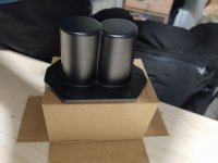
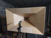
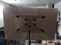
I've added hardfoam conefillers for testing (don't look the finish surfaces are ugly).
I measured inside ports and effectivly the upper range is better.
Also with the microphone capsule near the CD in the throat I've seen a difference. But meauring at the mouth ( I cant' meaures at 1 meter, my car box is full of room modes) nothing changed.
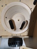
It seems that was right to implement cone fillers but this improvement is hidden by too long port to throat distance ( 10.7cm from throat to port center)
and also I've read in the dcx thread the acoustical measured pathlenght of the cd is 7,7cm.
the 2 ports for a side are 50cm2 so 1:10 of 1 driver SD and are frustrumized.
do I need to consider distance between br ports and throat right?
@Mark100
In your syn7 the ports are in flare center and also in cone center.
Do I need to consider cone center to port distance?
Because if I consider this (I don't to tranlate in english) the blanket is short
I need to rebuilt the 80° horn flares making this valutations and restart without BR ports that seems to dirty response like Art said.
Thank you
Ale
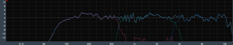
this is inside port GREEN NO FILLER-BLUE WITH FILLER
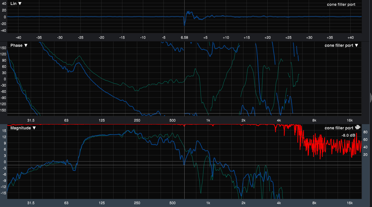
this is mouth and inside br port GREEN REFLEX PORT-BLUE MOUTH
 [/url][/IMG]
this is mouth + throat BLUE MOUTH- PURPLE THROAT
 [/url][/IMG]
@PELANJ I will look your sims as soon as I resolve my dilemmas. 😕
I've added hardfoam conefillers for testing (don't look the finish surfaces are ugly).
I measured inside ports and effectivly the upper range is better.
Also with the microphone capsule near the CD in the throat I've seen a difference. But meauring at the mouth ( I cant' meaures at 1 meter, my car box is full of room modes) nothing changed.
It seems that was right to implement cone fillers but this improvement is hidden by too long port to throat distance ( 10.7cm from throat to port center)
and also I've read in the dcx thread the acoustical measured pathlenght of the cd is 7,7cm.
the 2 ports for a side are 50cm2 so 1:10 of 1 driver SD and are frustrumized.
do I need to consider distance between br ports and throat right?
@Mark100
In your syn7 the ports are in flare center and also in cone center.
Do I need to consider cone center to port distance?
Because if I consider this (I don't to tranlate in english) the blanket is short
I need to rebuilt the 80° horn flares making this valutations and restart without BR ports that seems to dirty response like Art said.
Thank you
Ale
this is inside port GREEN NO FILLER-BLUE WITH FILLER
this is mouth and inside br port GREEN REFLEX PORT-BLUE MOUTH
this is mouth + throat BLUE MOUTH- PURPLE THROAT
Last edited:
@Mark100
In your syn7 the ports are in flare center and also in cone center.
Do I need to consider cone center to port distance?
Because if I consider this (I don't to tranlate in english) the blanket is short
I need to rebuilt the 80° horn flares making this valutations and restart without BR ports that seems to dirty response like Art said.
Thank you
Ale
this is inside port GREEN NO FILLER-BLUE WITH FILLER
https://postimg.cc/yg5CD74X
this is mouth and inside br port GREEN REFLEX PORT-BLUE MOUTH
[/url][/IMG]
this is mouth + throat BLUE MOUTH- PURPLE THROAT
[/url][/IMG]
It looks like your reflex ports are working well, for lowering response.
When you get all done, i'll be very interested in their final size and distance, from throat.
I do not know what is technically correct, as to distance between CD and cone. Whether it's to the port, or all the way to driver coil, or to the driver's acoustic center for the intended passband. (Same problem determining the technically correct CD end.)
I've read TD say, the narrowing throat presents a stiffer acoustic load, and typically measures a shorter than physical distance. Which would mean the HxV angle could vary that phenomenon too.
So lots going on i don't know still...
I've learned from a pragmatic point of view, that the notch seems to correlate pretty well with simple port-center to throat flange (along the horn wall).
So i go with that 🙂
The reflex ports are another animal...not sure what's best there, as i've only built one box with them, (and the box i built that used mb12n351's didn't have reflex ports.) I REALLY am interested in what you end up with.
Hi Mark
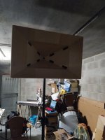
Tomorrow I want to detach DC and put a stiff plate against the cd adapter to simulate a cd with a diaphragm at S1 point of the horn and check if response changes. If changes I will consider cd pathleght also in my calculation.
Another curious thing is that with live measurement of the midbass section only
I can tell if CD amplifier is on or off.
the CD diaphragms became reactive and the 300hz region gains 1db.
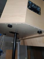
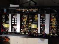
Today however wnet further with the carpentery. Installed folded handles,feet and 0-5 tilt pole mount. I was scared about was only 5° of tilting but with my KM 213 stands with hand crank I can achieve 2.5 meters and projection is good.
Bye
Ale
Tomorrow I want to detach DC and put a stiff plate against the cd adapter to simulate a cd with a diaphragm at S1 point of the horn and check if response changes. If changes I will consider cd pathleght also in my calculation.
Another curious thing is that with live measurement of the midbass section only
I can tell if CD amplifier is on or off.
the CD diaphragms became reactive and the 300hz region gains 1db.
Today however wnet further with the carpentery. Installed folded handles,feet and 0-5 tilt pole mount. I was scared about was only 5° of tilting but with my KM 213 stands with hand crank I can achieve 2.5 meters and projection is good.
Bye
Ale
Attachments
Looking great Ale.
Very nice looking work.
Yes, regarding effect on midbass, of amp on/off to CD.
With amp on, CD is shorted. (I usually just jump CD terminals together, unhooked from amp of course 😛)
It's amazing how much the CD acts like a passive resonator.
Sometimes i wonder if folks realize how much our measurements are effected by un-shorted drivers, or nearby speakers....
Hey, here's a fun measurement for trying to nail down distance between CD and cones. ......for determining notch, acoustic centers, etc.
Use the CD's lower section as the measurement microphone, and capture time-of-flight with Smaart's delay finder, while driving the mid cone(s).
You can even use the CD's higher section as a microphone, but the signal will be lower.
Or use the CD low vs high sections to get precise delay between CD sections. (0.07ms for dcx464)
Even using the mid cone(s) as a mic works....and it matches the TOF from CD found with CD as mic .....i likes to play around 🙂
Mark,Use the CD's lower section as the measurement microphone, and capture time-of-flight with Smaart's delay finder, while driving the mid cone(s).
Or use the CD low vs high sections to get precise delay between CD sections. (0.07ms for dcx464)
Even using the mid cone(s) as a mic works....and it matches the TOF from CD found with CD as mic .....i likes to play around 🙂
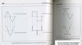
A loudspeaker can be used as a dynamic microphone.
In Sams "Handbook for Sound Engineers, The New Audio Cyclopedia" (second Edition), Glen Ballou explains the mechanisms that determine the 90 degree theoretical phase displacement of a dynamic microphone.
I’ll paraphrase what he said involving particle displacement, particle velocity, and particle acceleration.
Picture an electrical sine wave, start point “A” on the line, “B” above the line, “C” on the line again, “D” below the line, “E” back on the line.
At maximum pressure “B”, the diaphragm is at rest, no velocity. As the pressure wave crosses “C”, the diaphragm and coil reach maximum velocity, hence maximum electrical amplitude, 90 degrees later.
A condenser (capacitor) microphone's electrical signal matches the acoustical waveform with no phase lag, a good reason to use them for acoustic measurements 😉.
Art
Attachments
Last edited:
Aaah, good points ...thanks Art.
I have that book, along with the 5th edition too. Need to spend some more time reading them lol.
When i was a teenager in the late 60's, my folks house had speakers in all the rooms.
I learned how to use them as microphones, wired back to my bedroom for eavesdropping...heard/ learned some things i still want to forget 😱
😱
I have that book, along with the 5th edition too. Need to spend some more time reading them lol.
When i was a teenager in the late 60's, my folks house had speakers in all the rooms.
I learned how to use them as microphones, wired back to my bedroom for eavesdropping...heard/ learned some things i still want to forget
😱HI
I was busy.
I've rebuilt horn walls with smaller mid ports non frustrumized and as close as possible to the coax and no BR ports but with hardfoam cone fillers.
port center to throat is 7cm.
I post my BAD measurements ok this version ( no difference with coaxial or stiff alluminium plate in place of coax) 🙁
This version helped a little bit on 700hz but there is the same bad notch and another on 300hz.
The mid and hi response is worse than first version: not very linear and a bad dip in 8k region: tapping mid ports with masking take eliminates the dip so the problem are the closer mid port holes maybe beacuse are not frustrumized?!
The best total response is version1,very linear ( for me without fir dsp).
However I really want to build my ppsl sub sooner so I think I will use first version of horn flares with BR ports but with mobile caps for those
so I can close ports when Sub is present and open them when I need fullrange job (with eq)) from the synergies.
I'm thinking some magnetic wood caps or idraulic piston-like flanges with o-rings.
P.S. I've bought a Sinbosen K4-450 450x4 at 8ohm new shipped for 180euros for testing and maybe use it for dcx464s. First impression is positive.
Thank you guys for the support.
Ale
Attachments
Mark,
A loudspeaker can be used as a dynamic microphone.
In Sams "Handbook for Sound Engineers, The New Audio Cyclopedia" (second Edition), Glen Ballou explains the mechanisms that determine the 90 degree theoretical phase displacement of a dynamic microphone.
I’ll paraphrase what he said involving particle displacement, particle velocity, and particle acceleration.
Picture an electrical sine wave, start point “A” on the line, “B” above the line, “C” on the line again, “D” below the line, “E” back on the line.
At maximum pressure “B”, the diaphragm is at rest, no velocity. As the pressure wave crosses “C”, the diaphragm and coil reach maximum velocity, hence maximum electrical amplitude, 90 degrees later.
A condenser (capacitor) microphone's electrical signal matches the acoustical waveform with no phase lag, a good reason to use them for acoustic measurements 😉.
Art
Hi Art
So this phase rotation using cone driver like microphones is frequency dependant?
Thanks
I got a similar effect when I tried to make the ports smaller on my Runt clone. I just 3D printed various inserts and tested. Smaller hole meant lower output, but more HF. It all starts making sense to me somehow.
yes Pelanj
My sensation is using 12" drivers I could be satisfied keep the woofer high to 600hz, I use not synced BW 48/oct filters, 640hz on dcx 800hz on 12"s so I take advantage of 12"s acoustical roll off.
I've tried extreme close mid ports position to the throat, 2 different shapes of cone filler (but same material), frustrumized and non frustrumized ports, big and small ports.
12"s maybe cannot go so high in this configuration
I would definitively assemble them but leaving me free to make changes in the future. There are many many big screws and positioned in crucial locations favoring stiffness in this design, Is safe to leave them without glue?
Thanks
Ale
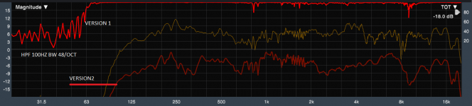
HI everyone!
I finally finished the tops. I put here response with and whitout wood cone fillers. no eq used.
BR ports added but I can close using magnetic cups.
I think I don't use cone fillers beacuse the total response is worse that having it and also I'm sure that the clearance of the cone movement is better, although the fillers are well sized for at least 7mm (6mm xmax and 39mm oneway xmech for the mb12n351).
I tried closing the up/down flares inside volumes and the BR frequency now matches my goal.
Now I can build the sub!😀
Happy Holidays
Ale
Attachments

Sorry pelanj this is the right plot. spl is shifted for better view.Which color is with and which without?
Thanks
Ale
Attachments

Thanks. I have a feeling that my badly designed cone filler did more harm than good. I need to try to remove it.
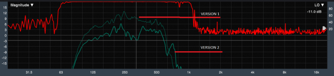
Question about crossovers.
Since this is my first audio project, this is also my first crossover setup.
I used the steepest order slopes available in my dsp (48db LR or BW) to preserv diaphragms movement for highest spl possible.
I used delay to match phase slopes in crossover regions using smaart. the flat fr response is obtained.
However I see that automatic impulse detection tool in smaart is different using low,mid,hi sections, it sets more delay compensation on woofers.
So I made separate plots in REW with activated crossovers and the result is: (1 picture).
If I tweak offset in rew for mid and low I shift impulses to match the first wave (2 picture- only for example, not precise settings).
If I use dsp delay to match the impulse response of 3 sections do I mathematically obtain mat5ched slopes in crossover region again?
My doubt that the steep crossover change too much the phase in crossover region and so is difficult to have both good IR and good xover overlaps.
do I give priority to good xover overlap?
Thanks
Ale
Hi Ale, i think you are doing some kind of awesome job for a first audio project !!!!
Phase traces that lay on top of each other at xover is the way to go, imo. Never fails, for either minimum phase or linear phase or any dang phase.
Aligning impulse response is tricky. For min phase like you are using, you want the starts of the impulse responses, where they first rise from 0dB to be the time alignment, and not the impulse peaks.
And it's difficult to visually nail down the exact time of those starts, even zooming in.
Since you have Smaart, i strongly suggest you simply align phase traces. I like doing it in real time.
It's not too hard to do in REW, but Smaart makes it much easier ime.
And keep in mind, any high order IIR impulse is going to look wonky, even when perfectly time aligned.
Ale,Thanks. I have a feeling that my badly designed cone filler did more harm than good. I need to try to remove it.
Can't tell exactly what is going on with the cone fillers from the two different responses you posted, probably need to test in the far field before removal.
Attachments

HI ArtAle,
Can't tell exactly what is going on with the cone fillers from the two different responses you posted, probably need to test in the far field before removal.
this picture is wrong, this is an old measurement with the mic in the throat.
I posted the right in the next post.
However as soon as the weather will be good I will do some tests in a free field.
Thank you.
Ale
- Home
- Loudspeakers
- Multi-Way
- 2x12 and 1,4 coax CD Synergy