HI
Is there a rule to calculate the multiple BR ports and also with different shapes? triangle square slot etc...?
Is there a rule to calculate BR ports dimensions with limitited air noise
especially for a box with 2 high pressure drivers?
thank you
Ale
Is there a rule to calculate the multiple BR ports and also with different shapes? triangle square slot etc...?
Is there a rule to calculate BR ports dimensions with limitited air noise
especially for a box with 2 high pressure drivers?
thank you
Ale
HI
Is there a rule to calculate the multiple BR ports and also with different shapes? triangle square slot etc...?
Is there a rule to calculate BR ports dimensions with limitited air noise
especially for a box with 2 high pressure drivers?
thank you
Ale
weltersys has provided some great information on this subject - have a look at post 2 on this thread!
HI
Thank you. I was not clear. I would create BR ports into the synergy to help at 100-100hz with a port lenght of 1,5cm (wood height). In the syntripp the ports are big and placed into horizontal flares.
Is the best placement to limitate hf diffraction along horn walls?
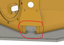
In my synergy I have limited space under the coaxial support. Maybe this(picture) can cause band pass problems or incorrect tuning?
Another question is about BR ports shapes , size for pressure created by 18ds115 at full power with limited noise form vents.
Is there also a rule to make 2 BR ports instead of one? Area divided by 2 for 1 port considering the 2 rear chambers are totally separated?
Thank you
Ale
Thank you. I was not clear. I would create BR ports into the synergy to help at 100-100hz with a port lenght of 1,5cm (wood height). In the syntripp the ports are big and placed into horizontal flares.
Is the best placement to limitate hf diffraction along horn walls?
In my synergy I have limited space under the coaxial support. Maybe this(picture) can cause band pass problems or incorrect tuning?
Another question is about BR ports shapes , size for pressure created by 18ds115 at full power with limited noise form vents.
Is there also a rule to make 2 BR ports instead of one? Area divided by 2 for 1 port considering the 2 rear chambers are totally separated?
Thank you
Ale
Attachments
hi Ale,
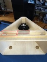
I've only used BR ports on one synergy, syn8 i called it.
It uses 8"s that simply didn't get down to 100Hz without the ports.
Here's how they fit in for one of the drivers.

The two ports together were about 1/4th of driver SD.
They needed to be out in the mouth....i remember they didn't work so well closer to the throat.
I've only used BR ports on one synergy, syn8 i called it.
It uses 8"s that simply didn't get down to 100Hz without the ports.
Here's how they fit in for one of the drivers.
The two ports together were about 1/4th of driver SD.
They needed to be out in the mouth....i remember they didn't work so well closer to the throat.
HI
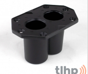
just for info I found a dual angle pole mount, alluminium casting
maybe is useful on synergies. If somebody is interested
Dual-tilt flange (0deg/5deg)
I will reply tomorrow to your posts.
Thankt
just for info I found a dual angle pole mount, alluminium casting
maybe is useful on synergies. If somebody is interested
Dual-tilt flange (0deg/5deg)
I will reply tomorrow to your posts.
Thankt
Attachments
HI
finally 18ds115 arrived. I found those in Italy for 400euros each. 😛
@Mark100
are The red parts in the picture made to gain ports lenght?.
I've made some simulations on winisd but if I mantain 1.5cm (wood walls) port lenght the areas of BR (1,2 or 4 ports)tuned to 100-110hz are small and the velocity is very high at high levels.
From a PA coverage perspective which position is better for BR ports? on horizontal or vertical horn walls?
@Art
In your syntripp ports are under the tweeter and to my eyes are not big.
How did you feel with ports velocity at very high level? Maybe the bigger rectangular ports in the horn help to mitigate air flux noise problems?
Thank you very much guys
Ale
Attachments
Ale,
I don't think the SynTripP large bass reflex ports would have much, if any affect on the entrance port noise contribution.
Any vent/port noise from high air velocity must be considered in relation to the SPL output of the speaker. If, for example, the ports are contributing 75 dB of wind noise at maximum excursion/port velocity, while the loudspeaker is producing 125dB, it's contribution would only amount to about 0.3% distortion, far less than the THD the loudspeaker produces at that level.
I don't think you can calculate noise directly from an air velocity plot.
At any rate, I have never been able to identify port air noise as a problem at high SPL unless there is no high frequency content to mask it.
Considering that there are literally hundreds (if not thousands) of commercially available MEH using relatively small entrance ports for woofers and/or midrange cones, it is not something I consider very important, though I still round the edges of the ports a bit just to ease my mind ;^).
Art
HI
@Mark100
are The red parts in the picture made to gain ports lenght?.
Ale
Yep Ale. The red parts make ducts with about the same cross sectional area as the ports in the horn. (they also help as extra bracing for the panels.)
Ditto to what Arts says about port noise relative to SPL.
It's often another area of over-concern-engineering imo.....
One of my favorite DIYs that gets high passed at 100Hz has ports that can really thump, and it adds a lot of positive appeal to the sound.
Port compression for the mid-range on a MEH shouldn't be a problem, though can be for bass reflex ports, hence the rather large BR ports of the SynTripP.
HI
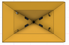
Finally I've made the BR ports mod like the left side of the picture.
Testing results in wrong BR frequency (90hz) even if I simulated 4 ports in winsid (I don't like very much) for 110hz.
Maybe I need only to fill the inside of the box with pink foam like Mark did. 😉
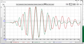
Crossover and delay was adjusted with Smaart looking drivers phase shift and slopes in the xover regions and is ok, No holes or strange dips.
The only strange this I put a little delay (0.30ms) to the woofers so I
did another step response in REW with xover activated. Maybe I'm in phase but some entire cycles behind.
I've filtered impulse both lows and mids at 630hz but it seems one of the impulses is streched and not only delayed. Same thing is I change frequency on both.
I't seems like doppler effect
I'm sure this is too strange for a newbie like me that there must be an easy explanation.
Thanks
Ale
Finally I've made the BR ports mod like the left side of the picture.
Testing results in wrong BR frequency (90hz) even if I simulated 4 ports in winsid (I don't like very much) for 110hz.
Maybe I need only to fill the inside of the box with pink foam like Mark did. 😉
Crossover and delay was adjusted with Smaart looking drivers phase shift and slopes in the xover regions and is ok, No holes or strange dips.
The only strange this I put a little delay (0.30ms) to the woofers so I
did another step response in REW with xover activated. Maybe I'm in phase but some entire cycles behind.
I've filtered impulse both lows and mids at 630hz but it seems one of the impulses is streched and not only delayed. Same thing is I change frequency on both.
I't seems like doppler effect
I'm sure this is too strange for a newbie like me that there must be an easy explanation.
Thanks
Ale
Attachments

Last edited:
Ale,HI
Finally I've made the BR ports mod like the left side of the picture.
Testing results in wrong BR frequency (90hz) even if I simulated 4 ports in winsid (I don't like very much) for 110hz.
The corner port location makes their effective length longer than would be simulated if wall proximity was not accounted for, so their area must be increased to raise the Fb to your desired frequency of 110Hz.
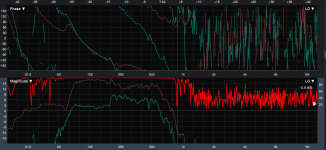
Not sure if I'm reading your chart correctly, but looks like the bass reflex ports are also passing a fair amount of (out of phase) content in the 500 Hz region. That content would clean up by lining interior reflective surfaces around the speakers with fiberfill or sound absorbing foam.
Fiberglass insulation is often pink, and works well (other than the itchy dust..) but most pink foam is closed cell, and would not be what you want to absorb the out of phase junk coming out the BR ports.
Art
Last edited:
I hope Ale will forgive me for entering his thread again. Art, the wall proximity effect might explain something. Would this be true also for the injection ports? In Hornresp, I get the calculated response much closer to the measured one when I enter around 2x the port lenght (just material thickness and maybe partly in the cone volume filler). Could this be explained by the proximity of the corner and end correction? I just played around with the sliders in the MEH wizard and I found this out.
Pelanj,
I think it is more likely that your "Klingon war ship" cone volume fillers are resulting in a larger VTC than you calculated, resulting in more of an acoustic band pass than anticipated. That said, your injection ports are also conically shaped, larger on the cone side than the exit size, don't know if you are, or may model that in Hornresp.
Art
Ok, that is the other cause I could think about. I have an idea how to improve this and use the volume of the fillers for shaping the ports. Thanks for pointing out! I should have tried without them first.
Hi
In my case I've found the lows are falling down too early and I don't like because for PA use I would squeeze the mids without knocking the membranes aganist the rod because of too low frequecies.
I could remake the vertical flares with this changes before glueing definitely:
1. mid ports structurally closest to the coax(I can move closer about 30mm,the suspension width)
2. make smaller mid ports( but today measuring inside the port i found the high roll off is the same measured at horn mouth, and the 100-200 region is good)
3. add aerodinamic cone fillers (glued one piece hardfoam).
4.move reflex ports closer to the cone baskets.
5. Make cone and reflex ports teardrops like relatively to the distance from the troat.
Maybe some points are useless?
I'm very happy for the results at this point but I feel I can get as much.
Ale
red is mic inside mid port.
green is at the horn mouth 😡
Attachments
Last edited:
- Home
- Loudspeakers
- Multi-Way
- 2x12 and 1,4 coax CD Synergy