Btw you are certain the 75k and 47k are configured like on your defective ampboards left chips 100k/20k, not like defective ampboards right chip 47k/75k ? So the right chips have flipped resistors if you compare both ampboards?
Wouldn't be a massive surprise if they decided to ship dual slave ampboards LOL
Wouldn't be a massive surprise if they decided to ship dual slave ampboards LOL
So what then is the best configuration for this board? I have the same board with R13 installed. Without R13 I get 36dB of gain and with it only 26dB? If R13 is simply removed you're saying the input z changes?
Rick
Rick
That will add to the feeling it is more powerfull than other 3116 🙂
Yes. Setting gain at 36dB is possibly a clever ploy by those in the Orient

I'm leaving the PCB as it is for the moment, to listen to music; soldering 1.6mm x 0.85mm components needs steady hands, which mine are not
Ummm ... on another DIY 3116 forum, you state that TI's value for the synch cap is incorrect. Curious ... what's your source of info? ... & what should it be, if not 1nF? Pity SMD caps aren't coded like resistors; too much information, probably, but even capacitance alone would be useful
To my aging ears, with my board being master/master, audio level from both channels appears to be the same. There would need to be a significant difference to pick the inbalance by ear ... & I've misplaced my SPL meter. The cheap Oriental pots don't help ... I've measured very significant resistance differences between the two tracks of many dual pots
 Notwithstanding, I believe that these amps are great value for the cost
So what then is the best configuration for this board? I have the same board with R13 installed. Without R13 I get 36dB of gain and with it only 26dB? If R13 is simply removed you're saying the input z changes
Look at TI's datasheet
r13 is there to connect synch from master (left) to slave (right), however the signal arriving at slave chip isn't recognisable, slave doesn't know what to follow. So removing r13 changes nothing, with or without you have not properly working slave chip. Now chinese remove r13 AND change gainsettingresistors, they select different gain and set both to master, see datasheet.So what then is the best configuration for this board? I have the same board with R13 installed. Without R13 I get 36dB of gain and with it only 26dB? If R13 is simply removed you're saying the input z changes?
Rick
On your ampboard you can remove r13 without any change. At the moment it is not functioning properly and without r13 is will function the same.
Many threads here, 3116 main thread first, share 10k/1nF filter not being able to give slavechip synch signal. TI support answered they were aware many moons ago and would update datasheet, they didn't, and they told to take values from TI 3116EVM, those were correct, 4k7/47pF. For fun use (Sample)RC Low-pass Filter Design Tool - Result -
and compare frequency respons for both RC filter, watch frequencyvalues below graph, shape is same 😀
and compare frequency respons for both RC filter, watch frequencyvalues below graph, shape is same 😀
For what it's worth
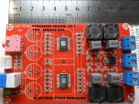
Pics of my July 2015 board which arrived DOA, electrolytics & large, single heat sink removed. It has has R13 & gain resistors are for 26dB, master/slave & 33uH inductors.
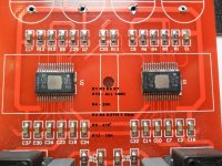
Second pic is a blow up of a section of the PCB, with resistor values shown ... for what it's worth 🙂
The board I later purchased, arrived a week or so ago, had no R13 & gain resitors are for 36dB, master/master & 10uH inductors
Both original & new PCBs show: XH-M190 V3
j.R.c
Pics of my July 2015 board which arrived DOA, electrolytics & large, single heat sink removed. It has has R13 & gain resistors are for 26dB, master/slave & 33uH inductors.
Second pic is a blow up of a section of the PCB, with resistor values shown ... for what it's worth 🙂
The board I later purchased, arrived a week or so ago, had no R13 & gain resitors are for 36dB, master/master & 10uH inductors
Both original & new PCBs show: XH-M190 V3
j.R.c
Attachments
Is pcb different? I mean there is one via for psu inner side chippins, in the middle of ampboard and the hole in pcb between chips seems right where picture shows bottom trace leading to that via. Is diode connected to switch (3 vias there that are probably in middle under brown color stuff that might not conduct)? Is switch working?
This thread has been dead for 6 months? Surely more must have experience with the XH-M190 board? 🙂
I just ordered 2 pieces, and will be building a bi-amp, for my B&W P5 speakers. Hopefully it will be powerful enough.
Will be turning back to this thread with the results at the end of the week.
I chose a 15A SM power supply. Hopefully not too noisy.
I just ordered 2 pieces, and will be building a bi-amp, for my B&W P5 speakers. Hopefully it will be powerful enough.
Will be turning back to this thread with the results at the end of the week.
I chose a 15A SM power supply. Hopefully not too noisy.
Last edited:
Need pictures of pcb and resistors underneath heatsink to know how to guide you. If chips are configured in master mode with resistors you can lower the gain by just removing R2 and leave it open. If they are in slave you have to desolder both R1 and R2 and place the lowest value on R1 and keep R2 open
I have one of those boards. Would recommend changing the capacitors. Mine blew. I need to look at chip pinout to figure out which of those resistors are R1 and R2(datasheet values).
If someone could point out the datasheet R1's and R2's on the above PCB it would be much appreciated :-D
Those capacitors are ready to blow.Hi Mortenhoe, Thanks for the offer to help. hear is a picture of my board.
Sent from my HT3 using Tapatalk
Caps on both my boards blew. They are not capable of 24v. I wrote to the seller Yoopar on ebay to either send capable replacement or a refund. Boards are probably fine with higher rate/better caps plus a reduction in gain.
Still need to figure out which resistors on the above picture is R1 and R2
Still need to figure out which resistors on the above picture is R1 and R2
These are the pcb manufactures markings. We need to figure out which of the 2 resistors above both chips (2 above each) is R1 and R2 in the TI datasheet. I bet someone on here can see it on the PCB. Im not entirely sure, but it might be R12, R10, R5 and R4 but I need this confirmed either by digging into the datasheet or by someone on here smarter than me(and theres quite a bit of those) 🙂
V4 of the board, no more sync, R13 and C33 are gone

Sold on amazon under the yeeco brand, $21 on amazon.ca and $17.13 on amazon.com
"Sanyo" WX 1000uF 35V caps, output traces seems wider than the V3
Sold on amazon under the yeeco brand, $21 on amazon.ca and $17.13 on amazon.com
"Sanyo" WX 1000uF 35V caps, output traces seems wider than the V3
V4 of the board, no more sync, R13 and C33 are gone
You can get the same board for cheaper if you are willing to wait for shipment from China:
DC12V-24V 100W+100W TPA3116 D2 Dual Channel Mini Digital Audio Amplifier Board | eBay
http://www.ebay.com/itm/2x100W-TPA3...ifier-Board-12V-24V-for-Arduino-/272395050466
Last edited:
- Home
- Amplifiers
- Class D
- 2x100W TPA3116D2 (2 chips, each in PBTL)