All rectifier tubes have a minimum Rt (total plate supply resistance per plate) which is specified in tube datasheets. Rt= Rs+n*n*Rp, Rs= DC resistance of secondary winding, n= transformer voltage step-up ratio, Rp= DC resistance of primary winding.
If Rt it is lower than datasheet specification it is the risk of sparks inside the rectifier tube and damage it
If Rt it is lower than datasheet specification it is the risk of sparks inside the rectifier tube and damage it

Suppose you have a capacitor input filter.
Suppose we have a first filter = 10 uF capacitor, 50 Hz power mains, and full wave rectification (4 diode bridge; or center tap and 2 diodes).
Full wave rectification charges that capacitor at a 100 Hz rate.
Xc = 1/(2 x pi x F x C)
F = 100 Hz
C = 10 uF
Xc = 159 Ohms (Xc = 133 Ohms if the power mains is 60 Hz [120 Hz charge rate to the 10 uF cap]).
100 times a second the rectifier is trying to charge 159 Ohms.
(You can do a similar thing, lift a 300 pound set of weights 1 time / second for 10 seconds).
The DCR of the power transformer primary times (the secondary voltage/primary voltage), and the DCR of the power transformer secondary, and the rectifier impedance limit the transient charging current.
If the rectifier is a tube, the transient current may be more than the maximum peak current rating of the rectifier tube . . . Ouch!
An additional resistor in series with the tube rectifier helps to limit the peak charging current.
4 out of 5 of my tube amplifiers use choke input filters; they do not use a capacitor input filter. The one amplifier with a capacitor input filter, soon will be changed to have a choke input filter.
Choke input filters do a few things, here are two:
The choke input filter drops more voltage than a capacitor input filter . . . the power transformer needs more secondary voltage to get the same B+ voltage as a capacitor input filter.
The choke input filter makes the power transformer run much cooler, than a capacitor input filter does (for the same B+ DC current load).
Last edited:
This transient current it is the reason why choke input filter sound better thank capacitor input filtre?
In case of fixed bias of 2a3 it is still present this transient current? I know that current it is stabile. I am right?
In case of fixed bias of 2a3 it is still present this transient current? I know that current it is stabile. I am right?
klauss00,
In General:
1. Capacitor input filter:
The volts out of a capacitor input filter can be as much as 1.4 x the volts rms.
But, the volts rms to the capacitor depends on the power mains voltage; and the various voltage drops due to the power transformer's primary DCR and secondary DCR, rectifier voltage drop, and any resistor between the rectifier and the input capacitor. All of those voltage drops are dependent on the DC load current on that input capacitor.
Because the capacitive current is high peak transient, the voltage drops due to DCR can be fairly large, the result is that 1.4 x factor is lower because of the lower volts rms that are applied to the capacitor.
Advantage:
Higher DC voltage out for a given rms volts from the transformer secondary.
Can be small, lightweight, and inexpensive.
Disadvantages:
Higher transient current.
Higher ground loop current, with lots of high frequency spectrum, potential hum and buzzing sound if the ground loop geting into the amplifier signal path.
Hotter transformer secondary windings for a given power supply DC current output.
2. Choke input filter:
The volts out of a choke input filter can be as much as 0.9 x the volts rms.
But again, the volts rms to the choke depends on the power mains voltage; and the various voltage drops due to the power transformer's primary DCR and secondary DCR, rectifier voltage drop, and the DCR of the choke. All of those voltage drops are dependent on the DC load current on that input choke.
Because the choke current is average (not high peak transient), the drops due to DCR can be small, the result is close to 0.9 x the volts rms are applied to the choke.
Advantages:
Lower transient current.
Lower ground loop current, with very little high frequency spectrum, low probability of hum and high frequency buzzing sound of the ground loop getting into the amplifier signal path.
Cooler transformer secondary windings for a given power supply DC current output.
Disadvantage:
Lower DC voltage out for a given rms volts from the transformer secondary.
Can be large, heavy, and expensive.
Care must be taken to prevent the magnetic spray of the choke from getting into the output transformer.
3. 2A3 amplifier, whether it is single ended, push pull, fixed bias, fixed adjustable bias, self bias, or battery bias . . .
Has constant quiescent current.
Single ended has relatively constant current for the linear signal power range of the 2A3 output.
Push pull Class A has relatively constant current for the linear signal power range of the 2A3 output.
Push pull Class AB has some large current draw for higher power of the linear signal power range of the 2A3 output.
Note: The capacitor After the choke input can have Lots of uF, so the larger current draw does not result in large B+ voltage variations . . .
except for long sustained full power output, such as 32 foot pedal tones of a pipe organ, or a really continuously loud rocking clipping style recording.
4. When you consider the "sound" possibly resulting from a capacitor input filter versus a choke input filter, just remember:
Potential ground loops egress into the amplifier circuits (large transient currents with larger voltages across the ground loops of capacitor input filters; versus lower average currents with lower voltages across the ground loops of a choke input filter.
Ground Loop Spectrum (low frequency plus high frequency harmonics of capacitor input filter; versus low frequency of choke input filter.
Last edited:
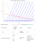
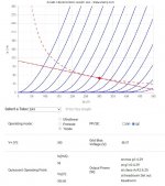
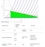
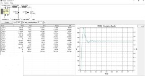
Meanwhile I've done some math. First I chose plate load 5k (because I have two Hammond 1627SEA). Second two operation points for 2A3; 250V, 60mA and 300V 50 mA (both with a Pa of 15 watts). With the help of vtadiy.com (https://www.vtadiy.com/loadline-calculators/vacuum-tubes-available-in-the-loadline-calculator/) I drew load line for both operation points, also I got grid bias -44V respectively -58.5V. Then I used all this data and the formulas published in RCA RC-12 and RC-15 to compute output power and 2nd harmonic distortion
Results:
1) for 250V, 60mA and -44V: P= 2.5W per tube and 1.61% 2nd harmonic distortion
2) for 300V, 50mA and -58.5V: P= 4.025W per tube and 3.4% 2nd harmonic distortion
Please note that vtadiy.com compute a 2.45W for first situation and 4.29W for second one.
Because it is a SE parallel total output power it is double but for 2nd harmonic distortion which is the value?
Attachments
Reading " Vacuum tune rectifiers by A. Shure", "RCA Radio Designers Handbook 4th Ed", "Power Supply Design for Vacuum Tube Amplifiers by Matt Renaud" I concluded that choosing the type of rectification like capacitor input filter, choke input filter, low DCR, low ripple depend mostly by the Class amplification, in Class A you can use what do you want but in Class AB or B it is strongly recommended to use choke input filter with low impedance vacuum tube.klauss00,
In General:
1. Capacitor input filter:
The volts out of a capacitor input filter can be as much as 1.4 x the volts rms.
But, the volts rms to the capacitor depends on the power mains voltage; and the various voltage drops due to the power transformer's primary DCR and secondary DCR, rectifier voltage drop, and any resistor between the rectifier and the input capacitor. All of those voltage drops are dependent on the DC load current on that input capacitor.
Because the capacitive current is high peak transient, the voltage drops due to DCR can be fairly large, the result is that 1.4 x factor is lower because of the lower volts rms that are applied to the capacitor.
Advantage:
Higher DC voltage out for a given rms volts from the transformer secondary.
Can be small, lightweight, and inexpensive.
Disadvantages:
Higher transient current.
Higher ground loop current, with lots of high frequency spectrum, potential hum and buzzing sound if the ground loop geting into the amplifier signal path.
Hotter transformer secondary windings for a given power supply DC current output.
2. Choke input filter:
The volts out of a choke input filter can be as much as 0.9 x the volts rms.
But again, the volts rms to the choke depends on the power mains voltage; and the various voltage drops due to the power transformer's primary DCR and secondary DCR, rectifier voltage drop, and the DCR of the choke. All of those voltage drops are dependent on the DC load current on that input choke.
Because the choke current is average (not high peak transient), the drops due to DCR can be small, the result is close to 0.9 x the volts rms are applied to the choke.
Advantages:
Lower transient current.
Lower ground loop current, with very little high frequency spectrum, low probability of hum and high frequency buzzing sound of the ground loop getting into the amplifier signal path.
Cooler transformer secondary windings for a given power supply DC current output.
Disadvantage:
Lower DC voltage out for a given rms volts from the transformer secondary.
Can be large, heavy, and expensive.
Care must be taken to prevent the magnetic spray of the choke from getting into the output transformer.
3. 2A3 amplifier, whether it is single ended, push pull, fixed bias, fixed adjustable bias, self bias, or battery bias . . .
Has constant quiescent current.
Single ended has relatively constant current for the linear signal power range of the 2A3 output.
Push pull Class A has relatively constant current for the linear signal power range of the 2A3 output.
Push pull Class AB has some large current draw for higher power of the linear signal power range of the 2A3 output.
Note: The capacitor After the choke input can have Lots of uF, so the larger current draw does not result in large B+ voltage variations . . .
except for long sustained full power output, such as 32 foot pedal tones of a pipe organ, or a really continuously loud rocking clipping style recording.
4. When you consider the "sound" possibly resulting from a capacitor input filter versus a choke input filter, just remember:
Potential ground loops egress into the amplifier circuits (large transient currents with larger voltages across the ground loops of capacitor input filters; versus lower average currents with lower voltages across the ground loops of a choke input filter.
Ground Loop Spectrum (low frequency plus high frequency harmonics of capacitor input filter; versus low frequency of choke input filter.
So 6A3sUMMER your amplifiers what Class they are?
I used to build Single Ended amplifiers.
All SE amplifiers are Class A
Now all my amplifiers are push pull, self inverting push pull, or balanced.
Some are Class A, and some are Class AB.
Only one of my amplifiers B+ uses a capacitor input filter.
I am going to modify that amplifier, and then all of my amplifiers will be choke input.
All SE amplifiers are Class A
Now all my amplifiers are push pull, self inverting push pull, or balanced.
Some are Class A, and some are Class AB.
Only one of my amplifiers B+ uses a capacitor input filter.
I am going to modify that amplifier, and then all of my amplifiers will be choke input.
Last edited:

- Home
- Amplifiers
- Tubes / Valves
- 2A3 SE parallel