The wire going to chassis is called center tap because it is the electrical center of both 375Vac ends. The connection conform your drawing is alright, you won't get shocked.
That 8uF capacitor has probably a short because of long time inactivety. If you want to power up the amp first make sure the caps are useable, as discussed earlier.
That 8uF capacitor has probably a short because of long time inactivety. If you want to power up the amp first make sure the caps are useable, as discussed earlier.
Thanks Disco
I'm taking it apart bit by bit and checking everything out.
Transformer is out and tested good, happy for that.
You mentioned using a 400v bench supply to reform the caps.
would it be possible to use the transformer and the 375 volt supply to do the same thing?
I'm taking it apart bit by bit and checking everything out.
Transformer is out and tested good, happy for that.
You mentioned using a 400v bench supply to reform the caps.
would it be possible to use the transformer and the 375 volt supply to do the same thing?
That's possible if you own a reliable HV cap or two, in the order of 10 to 100uF with a working voltage of no less than 500V.
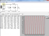
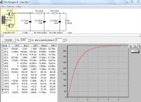
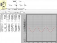
See attached example for a supply. Watch out for the heat coming from the 47 kilo ohm bleeder resistor as it dissipates almost 5 watt (use a thick 10 watt unit, or two 22K/5W series connected). After the 47K you connect your series resistor of 100K (5W) to the cap to recondition. Check out this free softeware: PSU Designer, it's a great tool.
Edit: See second example for 450V HT. Use 'fat' resistors or connect two or three in series to arrive at the appropriate resistance.
Attachments
Last edited:
There is a choke connected to Pin1 of the rectifier socket.
The other side connects to a lug ( seen in the image of the underside of the chassis bolted to and extending out from the coil. mounted on the right.) the lug has an 8 mfd cap connected also.
I haven't traced it back from that point yet. that'll probably be next on the list.
A choke does make sense here doesn't it?
I'm reading thru this now.
The 6n7 wiring:
+ input goes to pin 4 and is jumped to pin 5
The grids
- input goes to pin 3 and jumped to pin 6
The plates
6 volt from power transformer to pins 2 and 7
The heater
Pin 8 has a small resistor to ground and an 20mfd 450v capacitor to ground.
Pin 3 goes to a transformer that also has leads going to pin 3 (grids) of both 2A3 tubes.
Two other leads off of this transformer go to wiring lugs with resistors and caps that I haven't deciphered yet.
This would be a transformer coupled amp?
Attachments

Last edited:
yup. This transformer has a double function. First it couples the driver to the next stages. Next it turns a complete audio signal in two halves of opposite phase. Each 2A3 takes care of one phase while the output transformer blends the two phases together for driving the loudspeaker.
Thanks Disco,
I have a basic understanding of how the output transformer works and how to figure out the impedance to match the speakers.
The OPT from this amp has leads for the original speaker and then some unused leads that are unconnected. From what I know different leads are for different outputs and if it was wired for say, 16 ohms the other leads would be for 8 ohm or 4 ohm?
And is it possible at this point to determine the class of amplifier this might be?
Push Pull for sure I guess. But AB or B?
Should it have a decent sound or just loud?
Hard to say without knowing exact values but from the driver choice I'd bet on high power. With a feedback loop distortion can be tamed, if the interstage is up to the size of the correcting voltage. Meanwhile you could measure this interstage for voltage relation: apply 6Vac to the primary and see what comes out both secondaries.
I'll do that.
I checked the resistors and they all seem in working order and I've ordered all new caps
So I can put it back together.
Should be able to draw out a full schematic soon, hopefully.
Thank you for all your advice and suggestions and Merry Christmas.
Paul
I checked the resistors and they all seem in working order and I've ordered all new caps
So I can put it back together.
Should be able to draw out a full schematic soon, hopefully.
Thank you for all your advice and suggestions and Merry Christmas.
Paul
I found time to check the interstage transformer this morning.
6v (5.96) in gave me 15.85v out on the secondaries.
Earlier I said I had checked the resistors and they checked out ok. This might not be correct. I checked them in circuit and thought that would work.
After doing some reading I realized a few things.
I need to check them out of circuit.
I need to know what the original values should be.
They are hollow core wire wound ceramics.
I can make out some very light printing and hopefully I'll be able to get them out and into a stronger light and read what is there.
One does have Type AB written on it.
Any advice on checking these?
Is that 15,86V for both secondaries series connected, or do they have 15,86V each?
Wirewound resistors usually hold their exact value, unless they are much colored by long time overheating. The carbon part of carbon composit resistors may get moisty over time, or conductive channels might form from overdissipation. Equipment restorers dislike them for that reason while these are pretty good parts actually. If you want to know for sure, take each one out and measure with a DMM. 10% off might be just ok because the phase splitting is done pasively with a transformer.
Wirewound resistors usually hold their exact value, unless they are much colored by long time overheating. The carbon part of carbon composit resistors may get moisty over time, or conductive channels might form from overdissipation. Equipment restorers dislike them for that reason while these are pretty good parts actually. If you want to know for sure, take each one out and measure with a DMM. 10% off might be just ok because the phase splitting is done pasively with a transformer.
15.86 when I connect both secondaries, not each one.
I pulled the resistors out and got these values.
From right to left in the photo:
4.95 Kohm ( largest one , mounted to chassis)
830 ohm ( longest of the two in paralell)
812 ohm ( the shorter of the paralell pair)
20,000 ohm (20K) this is the only one with markings I can read.
It has 20,000 type AB printed on it.
They all seem to be in good physical condition.
I'll use these values to draw a schematic and see if it makes sense.
Thank you for your interest Disco,
Paul
Disco, and anyone else following along,
I"m drawing up a schematic and realized that the interstage transformer has 3 secondary wires. 2 go to the grids of each 2A3 tube (pin 3) and the 3rd wire goes back into the circuitry. I tested +/- 16 Volts across the two wires going to the 2A3 grids and 8 volts from each one to the center tap.
I"m drawing up a schematic and realized that the interstage transformer has 3 secondary wires. 2 go to the grids of each 2A3 tube (pin 3) and the 3rd wire goes back into the circuitry. I tested +/- 16 Volts across the two wires going to the 2A3 grids and 8 volts from each one to the center tap.
Regarding the third wire (coming from the interstage secondary) there are two options. Either it's going to a negative power supply to bias the final tubes. Or it's going to ground, in case the 2A3s are operated in autobias (with a resistor from filament to ground).
The input to output voltage for the interstage is 6:8 so the primary to secondary winding relation is 1:1,3+1,3.
The input to output voltage for the interstage is 6:8 so the primary to secondary winding relation is 1:1,3+1,3.
Thanks
Corrected that on this one ( not the one, see next post)
Corrected that on this one ( not the one, see next post)
Attachments

Last edited:

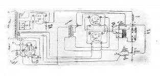
Correct the following post # 39 schematic:
1. The center tap of the interstage secondary is connected to B+
And
The center tap of the output primary is connected to Ground.
Swap those connections.
2. Ground one end of the output transformer secondary. Safety first.
3. Your input circuit needs fixing. It is not clearly drawn. Re-draw it.
A. You do not connect a - (negative) signal input to the 6N7 Plate(s).
The negative input needs to be connected to the ground.
B. You need a resistor from the + (positive) signal grid input to ground.
Last edited:
- Home
- Amplifiers
- Tubes / Valves
- 2A3 homebrew amp to rebuild for the education