6A3sUMMER,
I Worked on these:
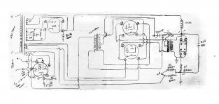
1. The center tap of the interstage secondary is connected to B+
And
The center tap of the output primary is connected to Ground.
Swap those connections.
2. Ground one end of the output transformer secondary. Safety first.
I think I have made these corrections , still not sure what's going on with my input situation.
I Worked on these:
1. The center tap of the interstage secondary is connected to B+
And
The center tap of the output primary is connected to Ground.
Swap those connections.
2. Ground one end of the output transformer secondary. Safety first.
I think I have made these corrections , still not sure what's going on with my input situation.
Attachments
If yo ureally want to learn about valve amplifiers then start from scratch with your own design. You need to learn about load lines etc.
Simply building something up teaches you little especially if it works first time.
Use LTSPICE for valve emulation and get it working there before going to hardware.
Simply building something up teaches you little especially if it works first time.
Use LTSPICE for valve emulation and get it working there before going to hardware.
Whoever made this home-brew amp must have had a signal source that connected a resistor across the plug from the signal source, which then connected to the input jack. That signal source resistor gives a DC return from the grids of the 6N7 to the bottom of the 6N7 self bias network (resistor and bypass cap) from the 6N7 cathode to ground.
Grids do not want to be floating, and do not want to be connected to the outside world without a DC return.
It appears that the input jack is grounded to the amp chassis.
The shield wire does not appear to be connected at the jack end; instead it is likely connected to the chassis at the far end of the shield, or other point that is also grounded to the chassis through a 3rd wire.
If you are going to use this amp with different signal sources, some of them will not provide a DC return for the 6N7 grids. You need to connect a single 100k resistor from the 6N7 parallel grids to the bottom of the 6N7 Self bias network (which is at ground).
It seems that the 0.01 capacitor that connects from the 6N7 parallel plates is connected to the tone control resistor (reostat?), with the other end of that resistor to ground. That is a variable high frequency tone control. Draw in the tone control (from the 0.01 cap to ground).
Or, the 0.01 cap connects directly to ground (fixed tone control).
Which one of those is how that part of the circuit traces out?
Last edited:
Paulslan1,
I've built a few amplifiers like this.
Can be really good but quality is limited by IT which is hard to get right, I have had three through this one amplifier of mine..
The better one renders sound akin to the SE amplifier but with 'wider' presentation. Not as visceral (as SE and DC coupling), but it can better control the back EMF which will be speaker dependant.
There is much to like about the circuit.
IME you would want to get it up and running, and then listen to it. Push Pull 2A3 can be really good. Hard to surpass, transformers depending. (but worth it)_
HK
Last edited:
Whoever made this home-brew amp must have had a signal source that connected a resistor across the plug from the signal source, which then connected to the input jack. That signal source resistor gives a DC return from the grids of the 6N7 to the bottom of the 6N7 self bias network (resistor and bypass cap) from the 6N7 cathode to ground.
Grids do not want to be floating, and do not want to be connected to the outside world without a DC return.
It appears that the input jack is grounded to the amp chassis.
The shield wire does not appear to be connected at the jack end; instead it is likely connected to the chassis at the far end of the shield, or other point that is also grounded to the chassis through a 3rd wire.
If you are going to use this amp with different signal sources, some of them will not provide a DC return for the 6N7 grids. You need to connect a single 100k resistor from the 6N7 parallel grids to the bottom of the 6N7 Self bias network (which is at ground).
It seems that the 0.01 capacitor that connects from the 6N7 parallel plates is connected to the tone control resistor (reostat?), with the other end of that resistor to ground. That is a variable high frequency tone control. Draw in the tone control (from the 0.01 cap to ground).
Or, the 0.01 cap connects directly to ground (fixed tone control).
Which one of those is how that part of the circuit traces out?
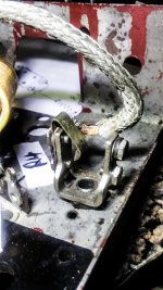
I know originally a Voice of America turntable was connected to the amplifier.
Maybe that's a clue?
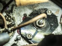
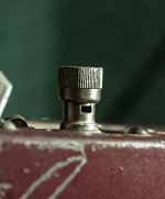
I've attached images of the tone control.
It is connected to the nut underneath the knob on top. That knob is all there is and it's not a potentiometer, more like a binding post of some kind.
Attachments
If yo ureally want to learn about valve amplifiers then start from scratch with your own design. You need to learn about load lines etc.
Simply building something up teaches you little especially if it works first time.
Use LTSPICE for valve emulation and get it working there before going to hardware.
I've loaded TLSPICE and I'm working my thru Mooly's tutorials.
I see what you mean about it being a great tool.
I have a long way to go but I have started lol.
Thanks for pointing me in that direction.
Paulslan1,
I've built a few amplifiers like this.
Can be really good but quality is limited by IT which is hard to get right, I have had three through this one amplifier of mine..
The better one renders sound akin to the SE amplifier but with 'wider' presentation. Not as visceral (as SE and DC coupling), but it can better control the back EMF which will be speaker dependant.
There is much to like about the circuit.
IME you would want to get it up and running, and then listen to it. Push Pull 2A3 can be really good. Hard to surpass, transformers depending. (but worth it)_
HK
HK
Since you have experience with and like this circuit can you shed any light on the input wiring?
6A3sUMMER is concerned about that part of the circuit.
There were Voice of Music turntables (VM).
I believe that Voice of America (VOA) refers to Radio Transmitters out side the US that are operated by the US.
VM turntables usually had Crystal or Ceramic phono cartridges.
The grid resistor to ground was probably 1 Meg to 10 Meg Ohm to preserve the bass frequencies from the Crystal or Ceramic cartridge, that would have been lost with a low resistance such as 100k Ohms.
When you use the amplifier with other signal sources, you need a grid resistor to ground.
You might use 100k, or up to 500k, depending on the input tube.
The post you photographed looks like it is connected to ground. Might be for connecting to the turntable chassis to reduce hum.
Careful, if it is connected to pin 3 plate, there is voltage there.
Last edited:
Just wanted let anybody that has been following along or offered advice know that things are moving forward.
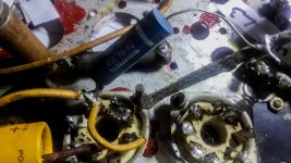
Transformer wires were cracked and very short so I have extended them and put shrink wrap over the exposed wires. Much was learned about soldering doing this.
I've also replaced all but one of the capacitors. the last one is a 20MFD that I will replace with 2 10MFD in paralell.
A note to any other beginner that may stumble across this thread.
I just happened to have this old homebrew amp so it was a good place for me to start. It has forced me to dig in deep and I have learned a lot, but I would start with an amp or DIY kit with documentation.
Paul
Attachments

Last edited:
what i do in such cases is to open up the ned bells and do the wire splicing inside, you can even use teflon wires and it will last a lifetime...a fresh coat fo paint of even powder cating will be awesome...
so then you can have a brand new looking power traffo, you can also do this with your OPT's...
so then you can have a brand new looking power traffo, you can also do this with your OPT's...
- Home
- Amplifiers
- Tubes / Valves
- 2A3 homebrew amp to rebuild for the education