I have an old 2A3 homebrew") amp I would like to rebuild and Learn a bit along the way.
amp I would like to rebuild and Learn a bit along the way.
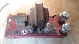
It has two 2A3's ,a 6n7 GT, and what appears to be an RCA 5u4g coke bottle, tubes. All numbering is gone on what I think is the 5u4g but I think it makes sense as a rectifier.
I tried to attach some pictures but each time I tried it locked my browser up.
So I guess first thing is how should I upload images?
End goal is to learn about tube amps and get it playing music.
Not looking for audiophile nirvana, yet
amp I would like to rebuild and Learn a bit along the way.It has two 2A3's ,a 6n7 GT, and what appears to be an RCA 5u4g coke bottle, tubes. All numbering is gone on what I think is the 5u4g but I think it makes sense as a rectifier.
I tried to attach some pictures but each time I tried it locked my browser up.
So I guess first thing is how should I upload images?
End goal is to learn about tube amps and get it playing music.
Not looking for audiophile nirvana, yet
I never thought to keep the chassis in it's original condition.
I see all the pictures of shiny new amps and t would sand it down a d put new paint on it.
But you're right I'll leave it as is.
On the transformers..
First thing I wanted to do was pull those off and check them out.
Could I get it running if they check out?
Then replace them later on?
I see all the pictures of shiny new amps and t would sand it down a d put new paint on it.
But you're right I'll leave it as is.
On the transformers..
First thing I wanted to do was pull those off and check them out.
Could I get it running if they check out?
Then replace them later on?
Just measure copper resistance of the primary (somewhere between 100 and 500R probably) and see if there's no short to the secondary. You'll have to reform the old elektrolytes: take a 5W 100K resistor and put it in between a single cap and a 400V bench power supply. Watch the current with a multimeter (for each mA there's 100v over the 100K) as it initially could rise to a couple of mA before setteling at a low value. If it's still high after 15 minutes it's probably beyond hope. They should run cool, if not discard.
Coupling caps can be checked with a meter, anything +20% should be replaced. If you do, try to find some period examples. Radio restorers keep 'm in old socks and gard them with a double barrel Too much of the old stuff gets thrown out while it's the antiques of the future.
Coupling caps can be checked with a meter, anything +20% should be replaced. If you do, try to find some period examples. Radio restorers keep 'm in old socks and gard them with a double barrel
Too much of the old stuff gets thrown out while it's the antiques of the future.
Last edited:
Well be sure to respect high voltage - if you've not worked on tubes before you need to learn the safety rules and rigorously follow them.
As a kid my grandad had an appliance/tv/radio store. All the old TV's ended up in a shed on our farm and I loved to poke around in there. My Dad and a switch
taught me the only thing I really know about tubes.....they can kill you.
I'll be careful

Just measure copper resistance of the primary (somewhere between 100 and 500R probably) and see if there's no short to the secondary.
I set my meter to 200 ohm and checked across the supply side leads and only got 3.2 ohms. Or did you mean to check between primary leads to the output leads?
If you carefully trace out all the wiring, you will learn something.
And others can see from your schematic what may need to be checked, replaced, etc.
One important thing, anytime you have applied power to an amplifier, those capacitors can hold a charge. That means that after the power is turned off, and the power cord removed from the wall, you still can get shocked.
A lot of old, and a lot of new, tube amps do not have bleeder resistors.
Be sure your amp does.
And be sure the caps are discharged before you get your hands and your Ohmmeter tracing out things.
Safety First.
Prevent the surviving spouse syndrome.
Nice find, for sure.
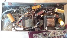
The hand-painted repurposed radio chassis does not have any collector or historical value but you may keep it after a good cleaning. Old home-use paint often has bad adhesion and it may flake of as soon as you touch it, check on a spot before going full steam with the cleaning. It is important to open the transformer end bells to check the insulation on the wires that go to the circuit, and check if there are any sign of flame or melting on the coils. Sadly many unrestored radios and amplifiers of this age have a burned out transformer because someone plugged them to see if they still work, and the power supply filter capacitor was shorted due to old age. You must check if there is any insulation loss between the transformer coils and the iron core. This is another common fault on old tranformers that does not have a plastic bobbin.
The hand-painted repurposed radio chassis does not have any collector or historical value but you may keep it after a good cleaning. Old home-use paint often has bad adhesion and it may flake of as soon as you touch it, check on a spot before going full steam with the cleaning. It is important to open the transformer end bells to check the insulation on the wires that go to the circuit, and check if there are any sign of flame or melting on the coils. Sadly many unrestored radios and amplifiers of this age have a burned out transformer because someone plugged them to see if they still work, and the power supply filter capacitor was shorted due to old age. You must check if there is any insulation loss between the transformer coils and the iron core. This is another common fault on old tranformers that does not have a plastic bobbin.
I got the transformer out this week.
Labeled all the leads as to where they go and built a dim bulb tester like this:
Dim Bulb Tester – Geek-Tips
I checked resistance across the input leads and read 3.2 ohms.
Plugged it in to the DBT and it tested fine. ( 40 watt bulb did not come on)
Heard a very low transformer hum.
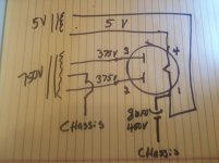
Transformer has 4 pairs of output leads.
Pair one (with center Tap) goes to pin4 and pin1 of the 5u4
Pair two goes to pin7 and pin2 of the 6n7
Pair three goes to pin2 and pin3 of one of the 2a3s
Pair four goes to pin1 and pin4 (cathode,right?) of the same 2a3 as pair three.
Another lead that has the same color code as the center tap on pair one isn't
really associated with any of the other leads ,it just comes out of the windings by itself. It goes to ground on the chassis.
I got a variac, superior electric 5 amp, coming this week.
When it gets here I will begin testing voltages across the secondarys.
Thanks for all the advice and let me know if Im on the right path.
Or not lol
Paul
.
Labeled all the leads as to where they go and built a dim bulb tester like this:
Dim Bulb Tester – Geek-Tips
I checked resistance across the input leads and read 3.2 ohms.
Plugged it in to the DBT and it tested fine. ( 40 watt bulb did not come on)
Heard a very low transformer hum.
Transformer has 4 pairs of output leads.
Pair one (with center Tap) goes to pin4 and pin1 of the 5u4
Pair two goes to pin7 and pin2 of the 6n7
Pair three goes to pin2 and pin3 of one of the 2a3s
Pair four goes to pin1 and pin4 (cathode,right?) of the same 2a3 as pair three.
Another lead that has the same color code as the center tap on pair one isn't
really associated with any of the other leads ,it just comes out of the windings by itself. It goes to ground on the chassis.
I got a variac, superior electric 5 amp, coming this week.
When it gets here I will begin testing voltages across the secondarys.
Thanks for all the advice and let me know if Im on the right path.
Or not lol
Paul
.
I was concerned about that.
The tubes may not be in the correct sockets.
I won't be powering it up anytime soon.
As soon as I figure out which voltages from the transformer are going to which sockets
I'll draw that up and post it here.
Hopefully that will provide a little more clarity.
Thanks for the warning.
The tubes may not be in the correct sockets.
I won't be powering it up anytime soon.
As soon as I figure out which voltages from the transformer are going to which sockets
I'll draw that up and post it here.
Hopefully that will provide a little more clarity.
Thanks for the warning.
TV isotap 25A arrived today and I had some time to check the transformer and everything seems in working order.
Here are the results on the secondaries:
750 volt pair with center tap
5 volt pair
2.5 volt pair with center tap
6.2 pair
From what I've found on the web this seems to be correct for a 2a3 amp.
I doubt this would have been a stereo amp always figured it to be a mono.
Any thoughts about which it might be?
I'll have more time this weekend to check the circuitry, just curious.
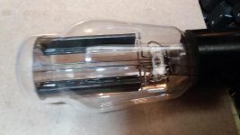
If there's a push pull OT (what I think it is) this would have been a mono amp since the 40s. Stereo is overrated anyway Beefy driver, can deliver some grid current.
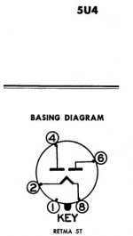
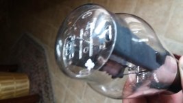
Beefy driver, can deliver some grid current.This is the tube I've been assuming was a 5u4g.
Before starting this thread I researched images of rectifier tubes that are frequently used in 2A3 amps and thought it was a 5u4 but now I'm unsure.
The lettering is completely gone and I've tried putting it in the freezer and fogging it and rubbing it in my hair lol. No luck.
Can anyone verify or identify?
I do have continuity across Pin 1 and Pin 4.
It is a 4 pin base not an 8 pin like some pictures I've seen of some 5u4's.
That is what got me wondering.
Thanks
Attachments
- Status
- This old topic is closed. If you want to reopen this topic, contact a moderator using the "Report Post" button.
- Home
- Amplifiers
- Tubes / Valves
- 2A3 homebrew amp to rebuild for the education