I'm not sure how you got in on RC filter. Maybe that is the thing, I dont know. It will cut off outgoing HF. If you want to ease up the ringings in the OPT tho, I think one can either experiment with zobels etc on the primary or, for the bold, introuduce some small GNF with a cap over the resistor.
I have to correct myself, after some reading I dont suggest this anymore. Though, here is a remark on the datasheet:
The source impedances used in the tables indicates a recommended upper limit, unless freq.
response can be compromised. At lower source impedance resonance peaking will occure. It
can be reduced using secondary load resistors.
Meaning, (cause theres no values proposed) one can try with increasing the load with resistors in series on the secondarys, starting with a few kohm and experiment upwards. Another try is to add small caps (a few nF) to that in series, making a zobel filter. Both might reduce ringings (better up the squarewave) in the higher regions.
Though, many people, including Per Lundahl says and also as earlyer suggested in this thread, to give the finger to the squarewaves let it ring, as it sounds better that way. This is a matter of taste ofc.
And also a little proof that squarewaves is squarewaves and music is music. And we usually dont listen to squarewaves.
Another thing can be to increase Rp with an extra anode load resistor. Tradeoff will be gain agaisnt damping.
Hey guys my Borbely 75W class A monos have an input impedance of 100K, that's open the way to use also an output cap🙂, time to experiment😎
What are the sonical differences to for example Top Flite Strata?
Sorry my ignorance what's Top Flite Strata?
What resistor value when used output cap, Iko use 330K & Andy use 1Meg?
Those guys has an output cap for the reason of blocking HV DC current from the anode. You have an OPT, so you dont need an output cap. For what reason would you put it there?
Due to the fact my power amps have an input impedance of 100K allows me to use an output cap so I'm a curios man, now I'm using 1Meg + 0,47uF as Thomas stated curves are more nice than with OPT, surely I install a switch to listen both ways: OPT & output cap.
No, without OPT as Iko did.
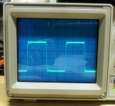
I don't know about you guys, but I can clearly hear transformer ringing. It gives a harshness to the highs.
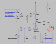
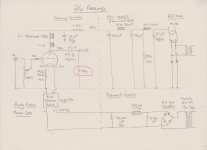
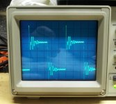
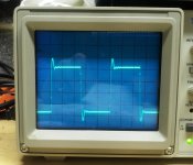
Here's an example of ringing on the input transformer of my 26 preamp (pic #1), which was cleaned up with an RC network on the secondary (pic #2) and series resistance on the primary (pic #3). The sound went from very harsh, to a little harsh, to smooth and clean going from picture 1 to picture 3. Ended up with 2nF and 850 ohms across secondary, and 800 ohms on primary.
Note that using a resistor across the secondary will drastically lower your gain, while using an RC will not.
I had a similar experience with the output transformer of my 2C22 preamp.
Note: these pictures are 10kHz square waves.
Attachments
Last edited:
Are you giving up on your output transformers? If you want to keep your output transformers then you cannot use an output cap.
Im in the mall. Look at suggested value for Ra for 150 v in the datasheet
I didnt find any suggested value in the sheets. Try 50 k. You might need to up the B+ to compensate for the fall over the anode resistor.
RC network on the secondary (pic #2)
Could you draw or explain this. Is it a classic RC or a zobel?
Best regards
Staffan
Could you draw or explain this. Is it a classic RC or a zobel?
Best regards
Staffan
Simple. R+C across transformer secondary. The best way to figure out the values (which are different for every transformer and circuit) is to use a small cap such as 1nF and a 5K or so pot in series across the secondary. Adjust the pot to get the best looking square wave. Then go up in capacitance to 2nF and do the same, then go to 3nF, etc. You want to choose the combination that has an acceptable square wave using the lowest C and the highest R. Once you have those values, substitute a fixed resistor for the pot. I like to use TX2575 resistors from Texas components for this, since they will custom make the resistors to whatever exact value you need; a little pricey but really, really nice low noise resistors.
I usually split the resistor value in two and use an RCR network, just so the resistors isolate the transformer from the cap somewhat.
In the case above, I found that the input impedance to the transformer was crucial to achieving the best performace, so I put a pot in series with the primary and adjusted that to get the best square wave after I optimized the secondary, then replaced the pot with a fixed resistor.
Are you giving up on your output transformers? If you want to keep your output transformers then you cannot use an output cap.
I want to try the both before deciding which to use🙂
- Home
- Amplifiers
- Tubes / Valves
- #26 pre amp