If I understand the VR circuit correctly you cannot parallel a large value cap to ground after the VR or you turn it into a pulse relaxation light. Cap value must be no more than .1 in value.
Do I stay with the one CCS before the VR tubes and then feed a choke and then the #26 plate?
Do I stay with the one CCS before the VR tubes and then feed a choke and then the #26 plate?
If I understand the VR circuit correctly you cannot parallel a large value cap to ground after the VR or you turn it into a pulse relaxation light. Cap value must be no more than .1 in value.
Do I stay with the one CCS before the VR tubes and then feed a choke and then the #26 plate?
Check the mentioned ecp audio project, I am sure he had to use an electrolytic to kill the hiss from the vr tube shunt and he doesn't use electrolytics unless he has to. Much of what you are dealing with is in that write-up.
In the article he mentioned he used two (2K) 20 watt power resistors in series with a 100 mfd cap between them
VR tubes cannot be used with large caps. 100nF max for most of them. I use a VR shunt reg in my 26 preamp currently and at very high volume there is a hiss, which I didn't have when I used my mosfet shunt regulator. But at the time the heat dissipated by the mosfet shunt reg bothered me.
Implement the Salas shunt reg if you want good performance and you're fine with the dissipated heat. As regal pointed out, there is/might be a GB going on for pcbs.
Implement the Salas shunt reg if you want good performance and you're fine with the dissipated heat. As regal pointed out, there is/might be a GB going on for pcbs.
But hey, you'll never know what we're saying if you don't try things. If you already got the VR tubes, it'll be an easy and cheap learning experience to plug them in your circuit. If you want to use a CCS before the VR tube, set it to about 40mA more than your load wants. If you will feed both channels from the same VR tube then you can set the CCS to about 55mA. You can then either load the 26 with a choke or with a CCS set to 5-7mA, depending on how you bias the 26.
right now I am gathering parts for two mono block power HV supplies and two mono block filament supplies.
I have Rod's boards finished and ready to use. I just ordered two cascode CCS boards.
I had plans to use a CCS before the VR tubes to eliminate the ripple. I haven't made my mind up yet if I want to go with a choke load on my 26 or go with a CCS there also.
Didn't plan on the Salas shunt regulator because I like the look of the VR tubes. I have plenty of the VR tubes and I have the chokes.
I also have the transformers for both the dual filament supplies and the two HV supplies. What I am missing and I wonder if I need them are the Hammond 157G chokes
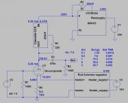
Ok, so if I use a power supply with some ripple and I run it thru a cascoded DN2450 CCS and then a VR shunt regulator stage I should come out with a ripple of 1mv or so. At this point would I not be good to go for a choke loaded #26. Would I be better off to ditch the choke and go thru another CCS and then the #26's plate?
It says I could have 100 volts of ripple and as long as the stayed above the 220v the CCS would reject all the ripple. They are saying they want to maintain 200 volts on the output.
So if I used a CCS before my VR tubes and a CCS to feed the plate of the #26 I would have 0 ripple at the plate of the #26? Is this correct?
This is exactly correct. I have a total of three stages of gain fed with a cascoded DN2540 CCS into VR tubes, with very very little noise on the output. You can have your ear touching the tweeter and just barely hear some 'water flowing'. Not at all annoying, and you don't hear a thing from your sitting position. I have had such good success with it, I use it all the time. I can measure better ripple reduction with the cascoded version over the single device, so go cascode.
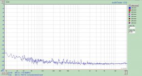
Noise floor of my 12B4 preamp attached. This tube has gained somewhat of a reputation for being noisy, yet I have a really low floor. What's not to like? 60 and 120 Hz is non-existent. The little spikes you see beyond 150 Hz are actually due to the tube used, not the power supply. Different tubes will show different little spikes (some are really quiet).
It's also nice to dissipate some heat above the chassis, instead of always having to deal with it under chassis.
Attachments
current calculation
Andy,
I can't reach the site attached. Would you post the curves/graph so I could learn a bit more. My 1660 is only 10mA and originally aim at the battery bias. I have all the resistors with me and want to go with the filament bias instead.
My 1660 10mA is a SE, not a pp. Does it make a lot of different.
Albert
http://frank.yueksel.org/sheets/127/2/26.pdf
There are the curves for the 26. 145v and 11.5v bias looks like 4.5mA. That's fine - well within the comfort zone since the 26 can tolerate up to 6mA. As you see from the curves, increasing the bias voltage does decrease the current at the same plate voltage. 13v bias would take you down to around 3ma. Whether these theoretical values from the datasheet work in practice is another matter, and might be affected by the condition of the tube.
Andy
Andy,
I can't reach the site attached. Would you post the curves/graph so I could learn a bit more. My 1660 is only 10mA and originally aim at the battery bias. I have all the resistors with me and want to go with the filament bias instead.
My 1660 10mA is a SE, not a pp. Does it make a lot of different.
Albert
Attachments

The only difference between ll1660 PP and 10mA is the core gap.
The PP has a little bit higher inductance and can tolerate about 5-6mA.
You should be fine.
The PP has a little bit higher inductance and can tolerate about 5-6mA.
You should be fine.
The only difference between ll1660 PP and 10mA is the core gap.
The PP has a little bit higher inductance and can tolerate about 5-6mA.
You should be fine.
What I worry is I don't know how to calculate the current/mA with filament bias. My plan is to run about 170v at anode and 18v dc to feed the filament. Would this be on the range??
18v raw dc for the regulator I suppose.
170v anode seems too much. With a 10ohm filament resistor you are going to have around 9-10v bias. Open the #26 datasheet see the loadlines and then set your operation point. 140-150v seems better, and you are going to have around 5mA then, depending on bias.
170v anode seems too much. With a 10ohm filament resistor you are going to have around 9-10v bias. Open the #26 datasheet see the loadlines and then set your operation point. 140-150v seems better, and you are going to have around 5mA then, depending on bias.
Quote:
I'm not sure use two CCS's this way, they will fight one another with tempeature dift and oscillate unless the first one is much bigger than the sond?
Question
If there is a Cascoded CCS before the VR tube regulation would two CCS's still oscillate? People are using a SSHV2 ahead of their Cascode CCS plate load.
Question
If there is a Cascoded CCS before the VR tube regulation would two CCS's still oscillate?
No. It takes 5 minutes to convince yourself of it if you already have the dn2540. You will learn a lot more from soldering four components than 4 pages of discussion here.
18v raw dc for the regulator I suppose.
170v anode seems too much. With a 10ohm filament resistor you are going to have around 9-10v bias. Open the #26 datasheet see the loadlines and then set your operation point. 140-150v seems better, and you are going to have around 5mA then, depending on bias.
Thanks and I'll follow all the numbers.
The reason I asked that I could control more closely if I know the formula for calculation.
Regards
What I worry is I don't know how to calculate the current/mA with filament bias. My plan is to run about 170v at anode and 18v dc to feed the filament. Would this be on the range??
Let's assume you have 1.05A running through the filament and that your bias resistor is 10R. The voltage differential between grid and cathode will be Vgk = I * R = 1.05 * 10 = 10.5V
Look at the data sheet for #26 and draw a vertical line at Vp = 170 volts. Assess roughly where the -10.5V curve crosses the vertical line and from that point draw a horizontal line that will cross the Y-axis. That will tell you roughly the plate current. Don't worry about decimals, there is enough variation between individual #26 tubes to invalidate any precision in your design.
Hey guys....I decided to join the fray....
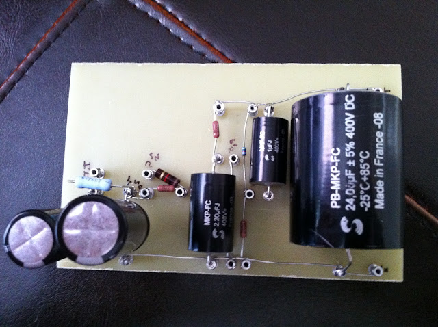
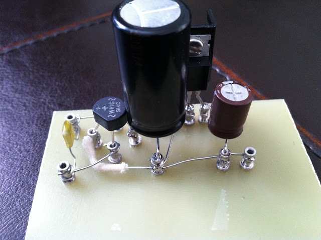
I stuck to Kevin's schematic as a starting point, and built up some boards over the weekend. I'll be using two chassis (PSU and Signal) as most are here. Some key points:
Silk TVC volume control
Tentlabs ultra-low noise filament supplies
Electraprint iron
I hope tonight to finish up the woodwork on the chassis, and start to make real progress ! Here's some photos of the boards:
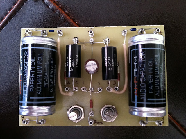
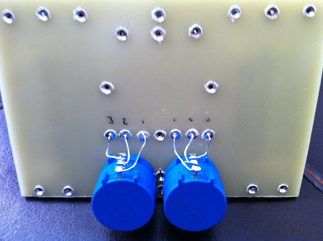
It seems a given that there will be noise issues.....My first approach will be to shield the boards in hammond enclosures (may or maynot help ?) under the chassis.
I stuck to Kevin's schematic as a starting point, and built up some boards over the weekend. I'll be using two chassis (PSU and Signal) as most are here. Some key points:
Silk TVC volume control
Tentlabs ultra-low noise filament supplies
Electraprint iron
I hope tonight to finish up the woodwork on the chassis, and start to make real progress ! Here's some photos of the boards:
It seems a given that there will be noise issues.....My first approach will be to shield the boards in hammond enclosures (may or maynot help ?) under the chassis.
Noise will come only from filament supply or proximity with transformers. My chassis is not fully shielded and I have no noise even with sensitive speakers.
You also might consider put the tvc at the output, as per Thomas Mayer.
Very nice build by the way so far!
You also might consider put the tvc at the output, as per Thomas Mayer.
Very nice build by the way so far!
Let's assume you have 1.05A running through the filament and that your bias resistor is 10R. The voltage differential between grid and cathode will be Vgk = I * R = 1.05 * 10 = 10.5V
Look at the data sheet for #26 and draw a vertical line at Vp = 170 volts. Assess roughly where the -10.5V curve crosses the vertical line and from that point draw a horizontal line that will cross the Y-axis. That will tell you roughly the plate current. Don't worry about decimals, there is enough variation between individual #26 tubes to invalidate any precision in your design.
ikoflexer,
Thanks N I benefit from this.
Albert
- Home
- Amplifiers
- Tubes / Valves
- #26 pre amp