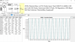
Updating myself...I have added 20% of the previous current in the PSUD2 case. I have also checked and found that the common mode chokes for the raw supply are 44H per coil, so have updated the inductance entry...assuming that the resistance per coil is ~0.5 ohm. If everything is as it was when I did the last determination of the bleeder, it should be 470R.I did not include a bleed current/resistor in the previous post...should be there. I'd say ~20% of current would give a resistor of 560-600R.
RC
I still have to check my assumption of 5% regulation for the Hammond trafo, 266L14...I have these to hand and will try to see how it powers up unloaded to get the real regulation %.
Best ! RC
Attachments
hi John, Yes, I have also heard reports of problems with 185 and 165 series from Hammond; but the 266 seems to be all good. Maybe they took the cost-cutting too far with the first two, such as flux density.For some reason the Hammond 185 series (or at least the ones I have) seem to have trouble, despite being split-bobbin.
Remind me though - are you having trouble with 60Hz breaking through, or 120Hz?
Hi Rod,Remind me though - are you having trouble with 60Hz breaking through, or 120Hz?
I will have a look at the 266 series. I know that is Hammond’s standard offering, and the 185 is the bare-bones budget option.
Funny, I don’t recall the pitch of the noise, now. (Slightly embarrassing.) It’s been a year since I had the 2P29L in the system.
I will get it out of storage and report back.
I’ve been wanting to hear it again, lately.
Best regards,
John
Hi,Hi Rod,
I will have a look at the 266 series. ...
I'm having a look at the pair of Hammond 266L14 transformers that I have...planning for a 2P29L line stage with filament bias. I am not too excited about what I have found so far. I have measured the DCRs of the primary and secondary coils...
Transformer 1 Primary: BLK-WHT 36.35 Ohm / BRN-ORG 43.7 Ohm
Transformer 2 Primary: BLK-WHT 38.30 Ohm / BRN-ORG 45.8 Ohm
Both transformer secondaries measured 0.3 Ohm.
I have yet to measure the no-load voltages of these two transformers...stay tuned.
RC
Last edited:
Well, I've measured the no load voltages and they are not as optimistic as I had assumed. With 117V primaries, both 266L14 seondaries measure 15.8 volts no load. That would place them at 12.8% regulation ... pretty far away from perfick. 🙂 I will revisit my PSUD2 calcs, to follow.
RC
RC
I also have had bad experience with budet Hammonds (186 Series 230V). They are buzzing at 50Hz (30% of max VA) and couple a lot of 50Hz into the floating supplies despite they are split bobbins.
Now I switched to Indel (only a EU-Option) which are inexpensive and work like a charm. In addition I upgraded to Rod's V9. With this setup the 2P29L (Filament Bias ~ 9V + 2.2V) is finally hum-free. No more batteries 😉
Now I switched to Indel (only a EU-Option) which are inexpensive and work like a charm. In addition I upgraded to Rod's V9. With this setup the 2P29L (Filament Bias ~ 9V + 2.2V) is finally hum-free. No more batteries 😉

Here's my PSUD2 for the 2P29L with updated Hammond 266-L14 regulation. I found that I could not get to 9v bias, but that I could get 6.2v bias. Rod, if you're watching this, could you please comment? This seems to be consistent with your private comment to me about the biasing the 2P29L:
"Hello Robert,
For 2P29L you can follow the app-note for 4P1L filament bias, exactly. It will mean a few extra volts at the Regulator input, but that is OK, for a 125mA DC filament.
So, if you do everything the same as the 4P1L, same transformer and all - you can switch between 2P29L and 4P1L , and enjoy the comparison.
The only precaution, to make this work, is that the 4P1L will draw more current at 160V, and it might be better to let it run down to 120V. but this might happen anyway, because of the plate supply impedance. but what would help, is to ensure that the plate supply can deliver 20mA, and preferably 30mA, if you want to make use of this opportunity.
Enjoy building with those Russian tubes!
best regards
Rod"
Best, Robert
Attachments
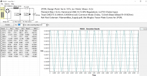
12.38V raw DC voltage is inadequate for R.C regulator (4-6V depends of version) + 5V filament + any voltage on filament bias resistor.
Robert, Please remove the choke, to get the desired performance. At 120mA load, there is little benefit from choke-input supplies anyway, so long as the PT→Diodes→Capacitor wiring is made according to the RC-V9 regulator's manual.Rod, if you're watching this, could you please comment?
If you do that, you can get as much as 21V DC from your 266L14.
If you are targeting 9V bias and the 2.2V of the filament voltage, set the DC input to around 16-18V (extra headroom for very low-current filament bias allows wider adjustment range, and the low current does not burn high power in the regulator's power transistor).
To reduce the voltage from 21V, you can simply increase the value of the dropper R (R1 in PSUD2; R2 + R3 in the Raw DC board).
That's a very useful confirmation - Thank you for the post!I also have had bad experience with budet Hammonds (186 Series 230V). They are buzzing at 50Hz (30% of max VA) and couple a lot of 50Hz into the floating supplies despite they are split bobbins.
Now I switched to Indel (only a EU-Option) which are inexpensive and work like a charm. In addition I upgraded to Rod's V9. With this setup the 2P29L (Filament Bias ~ 9V + 2.2V) is finally hum-free. No more batteries 😉
Could we have the Indel part number, please? I would like to try some of these.
My RC-V9 filament regulator was designed (among other things) to improve the rejection of 50Hz leakage.
If the 40VA is enough I usually use TS40 family.
https://www.tme.eu/en/katalog/trans...d_params=101:1445764;444:1445638;445:1445082;
https://www.tme.eu/en/katalog/trans...d_params=101:1445764;444:1445638;445:1445082;

Hi euro 21, Rod,12.38V raw DC voltage is inadequate for R.C regulator (4-6V depends of version) + 5V filament + any voltage on filament bias resistor.
Thank you both for your thoughts on this.
I was using 4V headroom, V8 boards and the 2P29L Triode filament is 2.2V, 120mA, not 5V filament. 12.4V - (4V+2.2V) = 6.2V bias. Ia + 120mA = 136mA through the filament bias resistor; Rfb=45.6 Ohm. No? Am I missing something?
Best, Robert
Voltage on filament bias resistor:
45.6Ohm*136mA= 6.2V
6.2V + 2.2V + 4V (R.C. headroom) = 12.4V
If R. C. V8 board working well at 4V headroom (I like greater values), it's OK.
p.s.
Estimated bias voltage is about:
6.2V + 9.17Ohm (half of filament) *0.136A = 7.45V
BTW I afraid that 16mA (trioded) current and -7.45V operating point is over the dissipation limit.
If you raise the filament bias resistor to 50-51 Ohm, the current would be decreasing, and dissipation too (10-12mA anode current).
The choice of the operating point depends a lot on type of anode loading and required anode voltage swing.
Hi euro21,...
p.s.
Estimated bias voltage is about:
6.2V + 9.17Ohm (half of filament) *0.136A = 7.45V
BTW I afraid that 16mA (trioded) current and -7.45V operating point is over the dissipation limit.
If you raise the filament bias resistor to 50-51 Ohm, the current would be decreasing, and dissipation too (10-12mA anode current).
The choice of the operating point depends a lot on type of anode loading and required anode voltage swing.
Are you saying that the mid-point of the filament should be the "bias voltage" reference point? I have to admit that I am a bit confused on this, so any elucidation would be appreciated., there's a + end and a - end...where is the real bias?
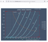
As regarding the anode+screen dissipation limit, my knowledge of this is that the limit is 2.7 Watt per Ale's traced plate characteristics, see attached. I do not see that "16mA (trioded) current and -7.45V operating point is over the dissipation limit".
As regards anode loading, I am considering either 1. ISO RC-160-15W Plate Choke with Miflex 0.33uF/600VDC output Cap, or, 2. LL1660/18mA line output transformer, Alt Q...if you have any thoughts on those.
Best Regards, Robert
Attachments
Geez Andy , yore changing your preferences weekly.🙂 Are you still listening to that 3" fullrange driver and use it to evaluate all designs??I prefer the 2P29L to the 26. But even better are the 10Y and 46. I just built all three. The 10Y is more smooth and "pleasant", the 46 is very clear and neutral. The 2P29L is somewhere in between - quite neutral compared to the warmish 26. I also tried the 47 in the 46 line stage and it wasn't as good as the 46. about the same level as the 2P29L, maybe a bit clearer and brighter but I don't think you gain much if anything. The 2P29L is very good, the 10Y and 46 are just a bit better, both quite addictive.
I don't think my basic views about DHTs have changed much in the 15 years or so that I have been building with them. My introduction to DHTs was the 26 and I will always have affection for that, but there is better. I used the 4P1L for many years but there was a certain something in the midrange that wasn't ever quite right so I stopped using it. It did have very good treble and bass and a low Ri. The 2P29L has very good midrange and just lacks a bit of sparkle in the treble, but it's worth using for the mids and it's the easiest to use. Moving on to the true triodes, the 01A and 10Y are both marvellous. The 01A poses some design challenges but there's no denying the sound quality. The 46 has always been a favourite - very neutral and clear. It's up there with the 10Y as a driver tube or preamp tube. Not quite a true triode, it nevertheless is wonderful. The 47 is a recent acquisition and not quite as good as the 46, though still a good DHT.Geez Andy , yore changing your preferences weekly.🙂 Are you still listening to that 3" fullrange driver and use it to evaluate all designs??
I was using a Mark Audio Alpair 10 but that's more like 5". I now use Wharfedale 2-way small stand mounts. I don't ever remember using a 3" fullrange speaker, that wouldn't make any sense.
In the case of filament biased DH tube the "cathode" (grid is more negative compared to the cathode) is indefinite. The best approach as "cathode" is the mid point of filament.Are you saying that the mid-point of the filament should be the "bias voltage" reference point? I have to admit that I am a bit confused on this, so any elucidation would be appreciated., there's a + end and a - end...where is the real bias?
ISO plate choke is good at series connection (160H, 1160R DCR, 20mA) with 160V B+.ISO RC-160-15W Plate Choke with Miflex 0.33uF/600VDC output Cap, or, 2. LL1660/18mA line output transformer, Alt Q...if you have any thoughts on those.
LL1660 is only 100H in Alt Q (4.5:1) configuration, so it's 12k57 impedance at 20Hz. For -about- 3k anode impedance tube it's -just enough, not too much.
- Home
- Amplifiers
- Tubes / Valves
- #26 pre amp