@king4joy
I have two separate chassis: one for PSU & the other for preamp, I suspect that the noise is more microphonic related than mains transformer related because the tubes arent isolated from metal chassis.
@neskor
I don't know is Erno Borbely Millenium 75W class A.
I have two separate chassis: one for PSU & the other for preamp, I suspect that the noise is more microphonic related than mains transformer related because the tubes arent isolated from metal chassis.
@neskor
I don't know is Erno Borbely Millenium 75W class A.
surely trafo mains hum
I don't understand why you wonders. 🙂
With choke/interstage you have about 30-40dB PSRR (for example at 100Hz), with CCS/gyrator 60-90dB. If you use R as anode load, all of PSU garbage (hum, noise) directly appears on the anode (0 dB PSRR), and interfere with signal!
You should understand the basics of electronics. 😛
I'm using two 10H chokes in the PSU + SSHV2!!!!
As you can see in the #3732 post (this is my #26 preamp schematic 🙂 ) I also use SSHV2, but after it there a cascode (DN2540) CCS!
The raw HT PSU is: 240V AC, AZ1 mesh, 5.4uF-10H-47uF-3H-220uF.
This is an old measuring (Spectrum__21.43.8.jpg).
50Hz component about 83-96dB, 100Hz component below 100dB!
DHT tubes are very sensitive things. If it's not well served, the result can be terrible.
Attachments

I have DN2540, what schematic do you use as CCS?
Using CCS as anode load you set SSHV2 for 40mA (20mA own reg + 20mA for #26), right?
Using CCS as anode load you set SSHV2 for 40mA (20mA own reg + 20mA for #26), right?
Last edited:
I have DN2540, what schematic do you use as CCS?
Using CCS as anode load you set SSHV2 for 40mA (20mA own reg + 20mA for #26), right?
Standard cascode CCS.
I attached all schematics (in zip file).
I use common HT raw supply and separated SSHV2 units (with about 20mA CCS).
I use two box layout (about 2m umbilical).
PSU box contains LT raw supplies, HT raw supply and two SSHV2.
Preamp box contains large heatsinks, R. C regulators, tubes, CCSs, input connectors and (Elma 3x) switch, and in my case S&B TX-102 TVC transformers (also with Elma 24x switch).
Attachments
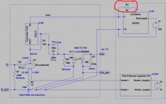
Thank you, sorry my ignorance attached pic to know if your R3 62R is the same R3 220R of SSHV2?
Merlin, you once again lost in the details. 😛
Look at the circuit solution.
As you can see this is my implementation of Salas shunt regulator. I use fix resistor for shunt's CCS, Salas (and its most common implementation TeaBag's PCB) use resistor paralleled trimmerpot.
The value of the resistor does not matter, because DN2540 Spice model not so accurate. It's sets in the real world -for example- 20mA current.
For your sake I measured in my (one of the many) TeaBags's type SSHV2 CCS bias resistor value: for 20mA it is 99 Ohm (300R paralleled -500R- trimmerpot).
The value of paralleling resistor is indifferent, it is only sets (with paralleled pot max. resistance) the minimum current of the CCS.
Last edited:
euro21......can I use a 1:1, 365R : 365R, 100H interstage transformer in place of the S&B TX-102 ??
euro21......can I use a 1:1, 365R : 365R, 100H interstage transformer in place of the S&B TX-102 ??
Of course.....but what is the goal?
My implementation is parafeed circuit, cap coupling to the volume control TVC (and resonance reducing with resistors).
If you use (after the cap coupling) large inductivity, also will have resonance problems.
OK....S&B TX-102 is a volume control....now I know. 🙂
So I will stick to cap output then.....just that I have a pair of the interstage transformer.
What are the pro and con of taking the output from the ZOUT and from the OUT please??
So I will stick to cap output then.....just that I have a pair of the interstage transformer.
What are the pro and con of taking the output from the ZOUT and from the OUT please??
What are the pro and con of taking the output from the ZOUT and from the OUT please??
"Zout" output impedance is far lower, than "Out" impedance.
For SS power amp which out should I use??
And for tube power amp, should I use the other out, please??
And for tube power amp, should I use the other out, please??
- Home
- Amplifiers
- Tubes / Valves
- #26 pre amp