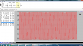
OK, disconnect the gyrator and use a resistor to drop your 200V to 150V, it should be something around 800 to 900 ohm 10W, and see what is going on, on the scope.
Maybe you can also try add a big cap between gyrator and 1660. With minus to ground, as a filter cap.
Maybe you can also try add a big cap between gyrator and 1660. With minus to ground, as a filter cap.
Thanks stajo, I do the measurements before the LL1660 so I suspect the problem is before the LL1660, Thomas Mayer told me not necessary the cap for this OPT in this configuration.
around 800 to 900 ohm 10W, .
How did you count. I would say like 10 k half a watt.
OK, disconnect the gyrator and use a resistor to drop your 200V to 150V, it should be something around 800 to 900 ohm 10W, and see what is going on, on the scope.
I have 307VDC in place of 200VDC
How did you count. I would say like 10 k half a watt.
Hey guys I ned to drop 307VDC to 150VDC, who knows the reistor value?
I have 307VDC in place of 200VDC
Then find a way to drop your voltage and test without the gyrator.
Listen also to Stajo. Put a cap temporarily between gyrator and transformer, other leg to ground to see if something changes.
These are the tests I would make.
I would recommend that you do not try to "patch" it. Stop for a moment, and think of a proper solution.
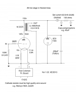
For instance, if you want to use your output transformer, this is what you can do. Use a VR150 tube to get 150V at the transformer. Feed the VR150 tube with a DN2540 as a CCS set on 35mA max. Feed the DN2540 CCS with filtered 200V DC.
For instance, if you want to use your output transformer, this is what you can do. Use a VR150 tube to get 150V at the transformer. Feed the VR150 tube with a DN2540 as a CCS set on 35mA max. Feed the DN2540 CCS with filtered 200V DC.
You are right, I miscalculated the current!How did you count. I would say like 10 k half a watt.
Hey guys I ned to drop 307VDC to 150VDC, who knows the reistor value?
157 volts divided by 0,005 A = 31,4 k. But then you really need a cap also cause this will act as anode resistor on top of your OPT. Which the gyrator also kind of does, but more like an inductor ie a choke. Now you have two "inductors" in series.
Last edited:
I would recommend that you do not try to "patch" it. Stop for a moment, and think of a proper solution.
For instance, if you want to use your output transformer, this is what you can do. Use a VR150 tube to get 150V at the transformer. Feed the VR150 tube with a DN2540 as a CCS set on 35mA max. Feed the DN2540 CCS with filtered 200V DC.
Sorry Iko I don't understand you, could you draw a schematic? BTW I don't have any VR150 tube🙁
I think he means to think your PSU circuit thru. Why do you have 307 volts into the circuit? Its way to high and is only getting you a to slow B+ with a lot of overkill resistors in the way.
How is your PSU made up?
How is your PSU made up?
Look in this thread for Andy's schematic. It is a really good solution, tried and true. Two VR75 tubes in series also work great, not to mention their glow is beautiful. I know it's frustrating because you're so close, but don't rush.
At the moment, if you really want to see it working, drop the voltage as the other guys said. But you'll need to fiddle a bit with the resistor values. Don't risk, use a power resistor. You will also need a high voltage capacitor, from the input to the transformer to ground.
At the moment, if you really want to see it working, drop the voltage as the other guys said. But you'll need to fiddle a bit with the resistor values. Don't risk, use a power resistor. You will also need a high voltage capacitor, from the input to the transformer to ground.
Oh, and please post a drawing of the PSU schematic, including the power transformer AC voltage. See, I told you from the beginning, you need to show the entire circuit. It's all connected.
I think he means to think your PSU circuit thru. Why do you have 307 volts into the circuit? Its way to high and is only getting you a to slow B+ with a lot of overkill resistors in the way.
How is your PSU made up?
Attachments
Iko wrote exactly what I was going to write - here's the schematic. I don't know if you need a grid stopper.
Thank you Andy.
- Home
- Amplifiers
- Tubes / Valves
- #26 pre amp