The ACP+ may work if your speakers are sensitive. I have an ACP+ and it is good for about 5Vrms output. So for 8 Ohm speakers, that is good for about 3W power.
It will not drive the amplifier to maximum power output though.
It will not drive the amplifier to maximum power output though.
Shade Common Gate Preamplifier
https://www.diyaudio.com/community/threads/schade-common-gate-scg-preamp.380487/
https://www.diyaudio.com/community/threads/schade-common-gate-scg-preamp.380487/

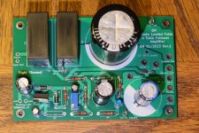
The revised PCBs finally arrived last week and I moved the parts of the original board onto the new board.
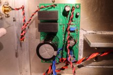
It's tested and up and running in my system, powering one channel, and my THF-51S Mu Follower Follower powering the other channel. It is sounding good with no surprises, sounding as it should.
Some pictures attached, with FFT results to come:
It's tested and up and running in my system, powering one channel, and my THF-51S Mu Follower Follower powering the other channel. It is sounding good with no surprises, sounding as it should.
Some pictures attached, with FFT results to come:
Attachments
-
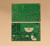 Tokin 2SK180 193V Follower Amp PCB R1 One PCB for Left and Right channels.jpg508.1 KB · Views: 200
 -
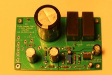 Tokin 2SK180 193V Follower Amp PCB R1 L1eft channel stuffed2.jpg269.4 KB · Views: 214
 -
 Tokin 2SK180 193V Follower Amp PCB R1 Left Board in Right Channel Chassis2.jpg483.9 KB · Views: 207
 -
 Tokin 2SK180 193V Follower Amp PCB R1 Left Board in Right Channel Chassis.jpg366.1 KB · Views: 199
 -
 Tokin 2SK180 193V Follower Amp PCB R1 Test Points Iq measurement.jpg401.1 KB · Views: 197

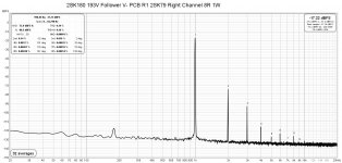
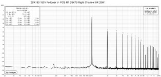
Here are the FFT measurements. 1W measurements were done with my ACP+ and 2SK79 preamps because the ACP+ has lower distortion than the 2SK79, but the ACP+ has very low maximum output. So the ACP+ measurement gives a better indication of the 2SK180 follower distortion. My standalone oscillator also has low output so a preamp is necessary. The 2SK79 preamp has high voltage output and high gain so it was used for the rest of the measurements. It is also what I use for listening so any listening impressions that I give are actually for the preamp-amp combo.
And by the way, the amp does not invert phase and H2 distortion is positive phase.
And by the way, the amp does not invert phase and H2 distortion is positive phase.
Attachments
-
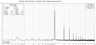 2SK180 Follower 193V V- PCB R1 ACP+ Right Channel 8R 1W.jpg240.4 KB · Views: 133
 -
 2SK180 Follower 193V V- PCB R1 2SK79 Right Channel 8R 1W.jpg240.8 KB · Views: 133
 -
 2SK180 Follower 193V V- PCB R1 2SK79 Right Channel 8R 5W.jpg241 KB · Views: 118
 -
 2SK180 Follower 193V V- PCB R1 2SK79 Right Channel 8R 10W.jpg241 KB · Views: 130
 -
 2SK180 Follower 193V V- PCB R1 2SK79 Right Channel 8R 15W.jpg240.9 KB · Views: 120
 -
 2SK180 Follower 193V V- PCB R1 2SK79 Right Channel 8R 20W.jpg241.7 KB · Views: 119
 -
 2SK180 Follower 193V V- PCB R1 2SK79 Right Channel 8R 25W.jpg243 KB · Views: 132
Not sure but perhaps the DC cable from switching supply to ACP+ picked up powerline AC? There are many factors that affect noise. Moving power and signal cables or components can change the noise. Perhaps environmental factors too (neighbouring electrical interference/emissions). Measurements were definitely not made under lab conditions in an accredited lab. 🙂
So noise and distortion measurements are for comparison purposes only and may not entirely repeatable. I also don't have a low, low distortion preamp so the distortion numbers are for the preamp/amp combination, and are not the distortion of the amplifier only. The other consideration is that Tokin SITs have large variation in distortion between samples. So unless the SITs are curve traced and matched, results for another 2SK180 in the same amplifier will yield different results.
However, the testing is good for check for errors. A while back I had finished the second channel of one of my amplifiers. Since the first channel test results were as expected, I only tested the second channel at 1W output, and it appeared good. So I put it into my system and listened to it for a few days. I finally got around to testing the second channel at higher power output levels and discovered that it was distorting heavily at much less than expected maximum power output. It turned out that I had connected the Tokin drain and source in reverse. I switched the connections around and the measurements were then as expected. Since my speakers are very sensitive, the amps were outputting 1W or less during normal listening so the mistake was not audible. The Tokin survived with no noticeable negative effects.
Now to work on the second channel.

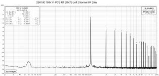
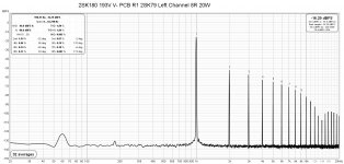
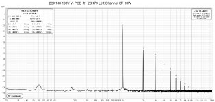
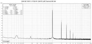
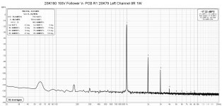
Distortion measurements for the left channel attached.
I am listening to both channels now and it is sounding very good. It's the usual SIT follower sound that I am used to - great clarity. The amplifier is non-inverting with positive phase H2. I prefer positive phase H2 so no need to invert the speaker outputs.
I am listening to both channels now and it is sounding very good. It's the usual SIT follower sound that I am used to - great clarity. The amplifier is non-inverting with positive phase H2. I prefer positive phase H2 so no need to invert the speaker outputs.
Attachments
-
 2SK180 Follower 193V V- PCB R1 2SK79 Left Channel 8R 25W.jpg241.5 KB · Views: 101
 -
 2SK180 Follower 193V V- PCB R1 2SK79 Left Channel 8R 20W.jpg241.3 KB · Views: 116
 -
 2SK180 Follower 193V V- PCB R1 2SK79 Left Channel 8R 15W.jpg239.5 KB · Views: 101
 -
 2SK180 Follower 193V V- PCB R1 2SK79 Left Channel 8R 10W.jpg238.7 KB · Views: 103
 -
 2SK180 Follower 193V V- PCB R1 2SK79 Left Channel 8R 5W.jpg238.9 KB · Views: 104
 -
 2SK180 Follower 193V V- PCB R1 2SK79 Left Channel 8R 1W.jpg240.9 KB · Views: 112
 -
 2SK180 Follower 193V V- PCB R1 ACP+ Left Channel 8R 1W.jpg239.6 KB · Views: 105

I've been listening to the amps and they're sounding great. I like all of my SIT follower amps but I especially like choke loading. The choke doesn't dissipate nearly as much energy as a current source, so lower power supply voltage and less heat sinking needed. Compared to a mu follower follower, the choke loaded amp has lower power output and a bit higher distortion. But my speakers are very efficient so the lower power is not an issue, and a bit more second harmonic distortion is not a problem - it may actually be a plus.
Now that the amps are done and working properly, I will share the Gerber files with diyAudio members who wish to build this amp. Also available are the power supply board files. Just let me know and I will send the files to you.
Now that the amps are done and working properly, I will share the Gerber files with diyAudio members who wish to build this amp. Also available are the power supply board files. Just let me know and I will send the files to you.
Attachments

- Home
- Amplifiers
- Pass Labs
- 25W Single Ended Hammond 193V Choke Loaded 2SK180 L'Amp