ahh, so my eyes did deceive me, carry on. Maybe a bit more space around those, as some people may get carried away with the lockwashers.
To Monk55, mgb1965, and everyone who may be interested in the PS boards, the amplifier boards are about to leave JLCPCB and make their way to me. I will hopefully be able to have the amplifier board tested in a couple of weeks. If you intend to order the amplifier board and PS board together, then I will send both files to you after the amplifier board is tested.

+1ahh, so my eyes did deceive me, carry on. Maybe a bit more space around those, as some people may get carried away with the lockwashers.
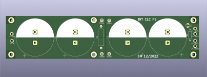
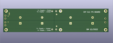
I did change it to provide a bit more space but I hadn't posted the images. So here they are (for the lockwasher people), not that I see a need for lockwashers to fasten a pcb:
Attachments
I have a tube stage that runs on the 40V rail - - and still delivers some 8 Vrms/22Vpp. Amplification something like 2Vpp. (?) Any interest?English please.
The gain required depends on the voltage of your source.
For the amplifier to output 25W into 8 Ohm, you need to input a signal of about 17Vrms to the amplifier. This takes into account that the full voltage input is not outputted by the amplifier. However most people don't listen to music with their amplifier outputting its maximum power continually. So in reality, you could probably get by with much less voltage output from your preamp, especially if your speakers are relatively sensitive.
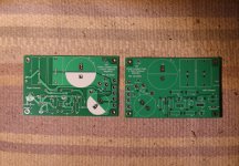
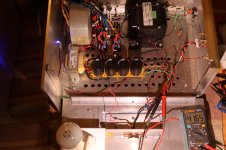
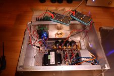
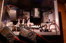
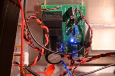
The boards were delivered on Christmas Eve and I finally got them stuffed and installed.
I'm still learning Kicad and trying different things, and that resulted in some silkscreen labels not getting on the Gerber files. I could have discovered the issue before ordering the boards if I had done a more thorough review of the Gerber files - lesson learned. Fortunately, the labels are only missing on one side of the board. So one channel is assembled, the existing power supply changed from V+ to V-, the power supply tested, and the board installed.
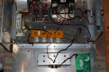
It is now powered up and has been running for about two and a half hours. Currently it is at design Iq of 2.5A, with V- at -37.5V and Vds at 35.0V.
Tomorrow I will do some power and distortion measurements. Hopefully there will be no problems.
I'm still learning Kicad and trying different things, and that resulted in some silkscreen labels not getting on the Gerber files. I could have discovered the issue before ordering the boards if I had done a more thorough review of the Gerber files - lesson learned. Fortunately, the labels are only missing on one side of the board. So one channel is assembled, the existing power supply changed from V+ to V-, the power supply tested, and the board installed.
It is now powered up and has been running for about two and a half hours. Currently it is at design Iq of 2.5A, with V- at -37.5V and Vds at 35.0V.
Tomorrow I will do some power and distortion measurements. Hopefully there will be no problems.
Attachments
-
 Tokin SIT Follower 193V PCBs-Missing silkscreen .JPG831 KB · Views: 208
 -
 Tokin SIT Follower 193V PCB stuffed.JPG736.1 KB · Views: 210
 -
 Tokin SIT Follower 193V PS Polarity Change.JPG909.3 KB · Views: 225
 -
 Tokin SIT Follower 193V Testing PS.JPG505 KB · Views: 206
 -
 Tokin SIT Follower 193V Setup-Bias adjustment.JPG400 KB · Views: 217
 -
 Tokin SIT Follower 193V Bias Adjust in progress-V-37.19V Iq 2.3A Vds 34.89V.JPG593.3 KB · Views: 202
 -
 Tokin SIT Follower 193V PCB in Amp.JPG411.3 KB · Views: 220
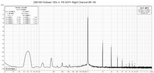
Testing turned up a major noise issue at 60 Hz and 180 Hz. Since I had revised the power supply, I checked it thoroughly but didn't find anything wrong with it. I then turned my attention to the bias voltage supply on the pcb and that was the source of the problem. That all took several frustrating hours but with the addition of a capacitor at the end of the bias supply, the noise is now at a much lower level.
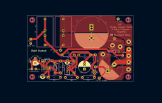
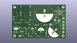
I have revised the pcb and hopefully this version will be the keeper. I'll review it again tomorrow and if I don't see any issues, I will order another five boards.
FFT-before and after, revised schematic and board attached:
I have revised the pcb and hopefully this version will be the keeper. I'll review it again tomorrow and if I don't see any issues, I will order another five boards.
FFT-before and after, revised schematic and board attached:
Attachments
-
 2SK180 Follower 193v V- PS ACP+ Right Channel 8R 1W.jpg237.3 KB · Views: 246
 -
 2SK180 Follower 193v V- PS 470uF ACP+ Right Channel 8R 1W.jpg234.9 KB · Views: 411
 -
 2SK180 Follower 193v V- PS rev1 Schematic.png23.8 KB · Views: 410
 -
 2SK180 Follower 193v V- PS rev1 top copper.png22.8 KB · Views: 397
 -
 2SK180 Follower 193v V- PS rev1 Board top.png59.3 KB · Views: 270
Hello,
I've been reading this thread for a long time and I can't wait to use my THF51 with your new Pcb.
I LIKE YOUR WORK.
I just read:
https://www.diyaudio.com/community/threads/sit-choke-loaded-follower.393966/
which on the main board integrates a buffer with DN2540. But I don't understand if this solution offers advantages when I then drive everything with a preamplifier that is able to supply current and directly drive the THF51s like the one that they used. or ACP+ or Aksa Lander or USSPA2 and so on.
What do you think about?
Regards
Guglielmo
Tokin SITs have high input capacitance. If your preamplifier driving it has high output impedance, the high frequency response may be affected. See My earlier post re: preamp output impedance. So an input buffer would solve that problem.
Once in a while a Tokin SIT with very high gate leakage current shows up and creates havoc in an amplifier, causing runaway quiescent current. One solution to that issue is to have a buffer in front of the SIT and move the SIT bias voltage from the SIT gate to the buffer gate.
However, if your preamp has low output impedance and if you don't have any problematic SITs, then an input buffer is not a necessity.
By the way the ACP+ has low gain and low voltage output, so it is not a good preamp for a follower amplifier.
Un buffer helps to solve possible Tokin problems. Read posts #511 - 514. A buffer also allows to add front end with high output impedance. Such as those using a 1 : 5 transformer.
27.5mm.
An update on the revised board - it has been fabricated and is now awaiting shipping. Perhaps I will have it by late next week.
An update on the revised board - it has been fabricated and is now awaiting shipping. Perhaps I will have it by late next week.
I picked up a pair of Papa's 2SK180s at Burning Amp, so I am watching this thread with interest. Ben, how would the B1Korg do as a front end?
-Tom-
-Tom-
"Edit: 2021-04-04 Added Information - Amplifier changed from Common Source to Common Drain (Follower)"
so, no bueno, you need full haroomph in preceding stage/preamp
so, no bueno, you need full haroomph in preceding stage/preamp
Hi Tom,
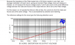
What Zen Mod said. Unfortunately the B1 Korg has very low voltage output. Since this amp is only single stage and has no voltage gain, it needs a preamp or gain stage that can output about 15Vrms to get full power output. Of course in real life, you can probably made do with less as most people don't max out their amplifiers but the B1 Korg's output is still too low.
The good news is that Nelson's latest DIY Front End 2022 is a good candidate for that.
Attached is the B1 Korg Distortion vs Output graph showing the low voltage output.
By the way, the new pcbs finally cleared Customs today so perhaps I will have them tomorrow. Shipping took quite a bit longer this time, probably slowed by Lunar New Year celebrations.
Attachments
- Home
- Amplifiers
- Pass Labs
- 25W Single Ended Hammond 193V Choke Loaded 2SK180 L'Amp