do I need to repeat last post?
I mean, I don't care am I smart or dumb in public ... and would I get shoulder tapping or not, just want to make your life easier, while we get tech. facts right

I mean, I don't care am I smart or dumb in public ... and would I get shoulder tapping or not, just want to make your life easier, while we get tech. facts right
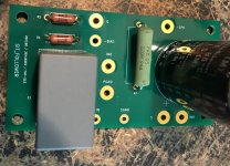
Got curious and slapped together a BAF2015 which is then easily converted to a follower. Perhaps not exactly what Ben Mah i doing here but i am still uncertain if 3A is enough for me and whether i should order a custom choke. So, this was just a comparison of common source vs a source follower using a THF51.
Listened to the BAF2015 only in active current load mode and not as mu follower in order to keep things simple.
My main system is biamped and the introduction of new amps is always painful so i did the listening in the bedroom system which has some hard to please speakers. Their impedance drops below 2.6 ohms and they are also highly taxing against any imperfections in the upper mids.
The BAF2015 was very impressive in many ways and especially in the reproduction of ambience and dynamics. Distortion is much higher than any other amp i have ever built and this was perhaps the reason it couldn't play convincingly any classical music. The dynamics otoh were truly surprising.
The Follower uses Mr Ciuffoli's ccs and simple biasing arrangement. The BAF2015 has a dedicated transformer and regulator for the bias. It will be essential to build a similar biasing circuit for the follower too.
The two amps sound unbelievably different. The Follower lacks much character and suffers some "sleepy Joe" syndrome with respect to dynamics but also sounds a lot more "normal". The improvement in distortion and damping factor is instantly obvious, plus a tube preamp works well with it due to the absence of Mr Miller. And it plays classical. It is the king of inoffensive but where is the BAF2015 magic?
As Mr Ciuffoli suggests it is possible to have the speaker return at V+ instead of ground and this provides a different and perhaps preferable sound. I must have chosen the wrong return point as there was an audible hum in that configuration.
Next will be to build a better biasing circuit and take some measurements.
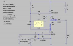
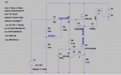
The circuits below are close to what i've built but not 100%. Some resistor values have been adjusted in situ.
Many thanks to Ben Mah for his research and enthusiasm and for starting the thread which caused me to actually get off the couch and build something. And of course to Papa for starting the SIT craze.
Listened to the BAF2015 only in active current load mode and not as mu follower in order to keep things simple.
My main system is biamped and the introduction of new amps is always painful so i did the listening in the bedroom system which has some hard to please speakers. Their impedance drops below 2.6 ohms and they are also highly taxing against any imperfections in the upper mids.
The BAF2015 was very impressive in many ways and especially in the reproduction of ambience and dynamics. Distortion is much higher than any other amp i have ever built and this was perhaps the reason it couldn't play convincingly any classical music. The dynamics otoh were truly surprising.
The Follower uses Mr Ciuffoli's ccs and simple biasing arrangement. The BAF2015 has a dedicated transformer and regulator for the bias. It will be essential to build a similar biasing circuit for the follower too.
The two amps sound unbelievably different. The Follower lacks much character and suffers some "sleepy Joe" syndrome with respect to dynamics but also sounds a lot more "normal". The improvement in distortion and damping factor is instantly obvious, plus a tube preamp works well with it due to the absence of Mr Miller. And it plays classical. It is the king of inoffensive but where is the BAF2015 magic?
As Mr Ciuffoli suggests it is possible to have the speaker return at V+ instead of ground and this provides a different and perhaps preferable sound. I must have chosen the wrong return point as there was an audible hum in that configuration.
Next will be to build a better biasing circuit and take some measurements.
The circuits below are close to what i've built but not 100%. Some resistor values have been adjusted in situ.
Many thanks to Ben Mah for his research and enthusiasm and for starting the thread which caused me to actually get off the couch and build something. And of course to Papa for starting the SIT craze.
Attachments

speaker return point is having nothing with THD spectra, it's all about ripple suppression
it's simple as that - follower is most likely being more linear arrangement, thus making your preamp dominant in picture
what you're gonna prefer, once when every detail done properly, only you can tell
it's simple as that - follower is most likely being more linear arrangement, thus making your preamp dominant in picture
what you're gonna prefer, once when every detail done properly, only you can tell
I have compared the 2SJ28 in common source and source follower modes and they are certainly different. I also have BAF2015 THF-51S amps. However, I have a 2SK82 Luminaria preamp and I run it with a healthy amount of 2nd harmonic and this influences the overall sound.
My speaker system is biamped and I find the BAF amps, with higher distortion, is great for the lower frequencies while the upper frequencies are better with the 2SJ28 follower. I much prefer it over the common source 2SJ28 amp. I think if I had a different preamp, my preferences would be different.
I am almost finished my 2SK180 follower amps, so very shortly, I'll be able to use it to power the lower frequencies and that will be interesting.
speaker return point is having nothing with THD spectra, it's all about ripple suppression
Of course, never thought otherwise.
My speaker system is biamped and I find the BAF amps, with higher distortion, is great for the lower frequencies while the upper frequencies are better with the 2SJ28 follower. I much prefer it over the common source 2SJ28 amp.
This makes a lot of sense. Best of both. Are you using the crossover cap as an output cap for the follower?
After reading Mr. Pass's comment regarding gate leakage current in my Common Drain THF-51S Mu follower thread(Single Ended Tokin SIT THF-51S Common Drain Mu Follower Amplifier , 45W?), I got curious about the actual gate leakage current of the 2SK180s in my amps. As I mentioned in post #194 I thought that it may be a possible cause of runaway issue.
Not sure, but maybe this is useful (THF51, not 2SK180).
I did measure the leakage current in one of my amps: 25W Single Ended Hammond 193V Choke Loaded 2SK180 L'Amp
It was very high - much, much higher than 0.1uA. It was 143uA. I think that perhaps I was just unlucky to get two bad samples.
It was very high - much, much higher than 0.1uA. It was 143uA. I think that perhaps I was just unlucky to get two bad samples.
No. I built a modified version of the LX-Mini cross-over for biamping.This makes a lot of sense. Best of both. Are you using the crossover cap as an output cap for the follower?
you must have zener, to protect from excessive negative gate voltage
I'm curious about this zener as well, Ben mentions in post #158 that it was problematic so he removed it.
exactly, A to gate, C to source
if something pulls gate down (ref. to source) , zener clamps to safe voltage
zener goes between G and S
it'll make problems if you put it in wrong way - from G to GND , and having both G and S flying above choke in Source, there goes problem
as I'm often saying - GND ( and references in general) is State of Mind
NB - being wise a$$ is not preventing me of making silly mistakes, here and there
last time was when developing LuDEF - couldn't bias cascode for God's Sake ...... only when I discovered that I referenced mosfet gate reference to its Source, instead to LU source ..... I did manage
Ikebana prototyping have its good sides, but also bad sides
So after reading these posts this morning, I decided to have another look at the problem. And I'm still baffled. I spent all of this morning checking things out and spent a lot of time this afternoon thinking about it but the zener is still causing problems, or something else is wrong and the zener is indicating that there is a problem.
I took one amp apart and had a close look at the circuit. Most of the circuit is the bias supply and I could not see any wiring errors there, nor any wiring errors in the actual amplification stage. Without the zener, the amplifier worked as I expected. V(gate to ground) - V(source to ground) = Vgs, so that was fine. Shorting the signal RCA jack did not change Iq.
Just to be sure that the 9V zener diode was installed correctly for this test, I used clip leads and made sure that they were attached to the 2SK180 gate and source, with cathode to source and anode to gate. With the input signal RCA open, I measured Vgs=-3.5V and Iq=2.0A (amp was not fully warmed up). When I shorted the input, Vgs=-3.0V and Iq=2.8A. So V(g to gnd) decreased as V(source to ground) increased, and a net decrease in Vgs.
I then installed two 9V zeners in series and connected them to the source and gate. With the input open, Vgs=-3.5V and Iq=2.0A. With the input shorted, Vgs=-5.0V and Iq=0.2A. So V(g to gnd) increased and V(source to gnd) decreased, and a net increase in Vgs. Adjusting the bias supply trimmer did not increase the current. I forgot to check Vgs but I assume that since Iq did not change, then Vgs also did not.
I measured no DC across the signal input RCA jack but I replaced the input coupling cap with another cap, tested again and the same results.
I also tested one zener and the reverse bias voltage was around 9V.
So I have no clue as to what is going on. Results today seemed to be the same as what I had previously. It should work but it isn't working. Also, when the amps were in common source mode, the zener did not cause any issues.
Is it related to the high gate leakage current of my 2SK180s? Or is it just coincidental?
So I finally gave up and put the amp back together without the zener. They are playing now and they sound great. If there is a wiring error in them, it certainly doesn't seem to affect the sound as far as I can tell.
So, a lost day, a day that I was originally going to spend amp building, and I am still baffled and clueless. It will stay an unsolved mystery as I will explore no further.
Hours later: I decided to give it one more go. I clip leaded a zener to the gate and source with the preamp connected, and turned the preamp on and then the amplifier on. No problem. I connected two zeners in series and no problem. I turned off the preamp and Iq dropped to 0.2A, same as when I had the input shorted.
I give up. Well, maybe some day I will take the 2SK180 out and install another Tokin and see if the problem is with this particular 2SK180 in this particular setup.
Sorry if this has discussed before, but is it possible that the Zener makes the thing oscillate? Can you check with a scope?
How very weird. Unless due to some fantastic coincidence both input caps have developed a leak i am also for oscillation. The zeners are adding some small capacitance and clearly there are some parasitics in the source. But where is the gain? A hundred ohm resistor across the choke to test this?
Last edited:
No issue without the zener, issue with zener installed. I will check for oscillation. It is possible that the bias supply with a LM337 regulator is somehow involved. I will investigate next weekend.
Thanks everyone for the suggestions.
Thanks everyone for the suggestions.
Next will be to build a better biasing circuit and take some measurements.
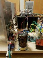
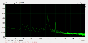
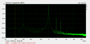
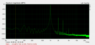
Added a bias transformer and regulator. A bit better sound but still made for comfort, not speed. Calm music sounds very nice, like a low distortion, high power 300B. A bit too rich on the cream.
The 3.12A bias allows for about 16W in 4.4ohms. The sink and the fan are not strong enough for more.
Df is a very decent 15.
Distortion in 1, 5, 10, 15W /4.4ohms
Attachments

Last edited:
could the the voltage cross the zener be anything between 0 and Vgs?
Does it have a small current going thru it?
Does it have a small current going thru it?
analog_sa, Great looking distortion profiles.
wwwttww, It's a 9V zener. The voltage at the source was 2.0V, so less than 9V. The bias voltage at the gate was negative. So current should not flow through the zener in either direction. The zener leakage current is in the order of micro Amps.
wwwttww, It's a 9V zener. The voltage at the source was 2.0V, so less than 9V. The bias voltage at the gate was negative. So current should not flow through the zener in either direction. The zener leakage current is in the order of micro Amps.
- Home
- Amplifiers
- Pass Labs
- 25W Single Ended Hammond 193V Choke Loaded 2SK180 L'Amp