Fortunately I had no problems with the THF-51S in my Sissy SIT version 1. No problems either with my BAF2015 THF-51S (pre-Singing Bush). Also no problems with a pair of THF-51S that I bought recently and tried in this 193V amp in common source mode. It was only the two 2SK180 that had high gate current. Just unlucky there.
Applying the bias through a choke instead of a resistor should also help. Perhaps 10-30H with a coil resistance in the region of 100ohms. Or a topology where the gate is driven from a transformer secondary which carries the bias.
A grid choke is a possible solution, especially in common source mode.
However since the 193V load choke is connected to the source in common drain/follower mode, it provides most of the bias voltage, plus any increase in Iq increases the bias voltage which offsets the Iq increase. So in follower mode it, is good.
However since the 193V load choke is connected to the source in common drain/follower mode, it provides most of the bias voltage, plus any increase in Iq increases the bias voltage which offsets the Iq increase. So in follower mode it, is good.
Gate Leakage Current
After reading Mr. Pass's comment regarding gate leakage current in my Common Drain THF-51S Mu follower thread(Single Ended Tokin SIT THF-51S Common Drain Mu Follower Amplifier , 45W?), I got curious about the actual gate leakage current of the 2SK180s in my amps. As I mentioned in post #194 I thought that it may be a possible cause of runaway issue.
So yesterday I got curious about the gate leak current of the 2SK180s in my 2S180 193V follower amps. First I looked up the Tokin specifications and they specified 100uA maximum at Vgs=-40V.
Mu measurements across 10k resistor at gate to bias supply:
at power up: 15mV
at 1 hour: 200mV (.20V/10k=0.020mA= 20uA gate leakage)
at 3 hours: 900mV (90uA gate leakage) Iq=2.48A
at 5 hours: 1.430V (143uA gate leakage) Iq=2.87A
At this point Iq was drifting up to 2.9A. It had been a while since I last check Iq and it seemed to have drifted so I adjusted it down to 2.8A and the voltage across the resistor dropped to 1.39V (139uA gate leakage). I continued the monitoring and it seemed to stabilize at about 1.3V+/- (130uA gate leakage) across the 10k resistor and Iq=2.75A. There was some drifting due to VAC variations at the wall plug. During monitoring the VAC was fairly high, varying between 121.1VAC and 122.3VAC.
So the measured gate leakage current was very high and in my mind was the probable cause of the stability issue of the amps in common source mode. A 1.43V drop across the resistor in series with the bias voltage reduces the bias voltage by that amount, thereby increasing Iq. In common drain mode, the 1 Ohm DCR of the 193V at the 12SK180 source provides the majority of the bias voltage and tames the runaway Iq. Others have had no issues with their 2SK180s so I think I was just unlucky to get a couple of bad examples.
I read that Pras noted the THD-51N was better temp compensated than the -51-S. You really need a DC feedback with such a drift.
It's behaving in follower mode with the 193V connected to the source. This experience inadvertently has opened my ears to single ended SITs in follower mode and I realized that I prefer it much more than single ended common source mode, so it is a happy ending.🙂
So far I really like the sound of the 2SK180 as a follower.
I'm getting hold of a pair of 2SK180 devices with a view to building the design in post #109. I'm assuming the 2SK180 will need to be biased at around 2.5 - 2.7A
I plan to use it to drive a full-range speaker in a Pass SLOB project. I am already working on a MoFo buffer and planned to roll-off the bottom end of the MoFo (to explore if I can dispense with a separate crossover hi-pass filter) by adjusting the the input capacitance and using a smaller choke.
As this is conceptually similar to the MoFo I'm thinking a similar approach should be viable. If I assume a first order Hi-pass CR filter with R=16K (R2, P1 (50%) & R3 in series), reducing C1 to 56nF will give me a -3dB point at about 180Hz. I'll need to see if I can find a suitable smaller value choke to experiment with for a reduced bandwidth implementation.
I'm no EE so will value any observations about this approach. Obviously, the fall back position will be to use a separate hi-pass filter.
You can experiment with the operating points. I chose Vds and Iq based on my testing of the samples that I had, looking at the power output and distortion profiles.
Choice of choke will depend on how much power you want. The 193V is rated at 3A. If you choose a lower inductance and lower current rated choke, it will affect the power output and frequency response.
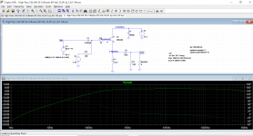
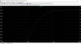
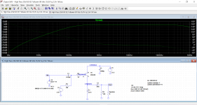
If you keep the 193V and the component values, then changing the input coupling capacitor value will change the low frequency response. I did simulations for 100nF and 56nF:
Choice of choke will depend on how much power you want. The 193V is rated at 3A. If you choose a lower inductance and lower current rated choke, it will affect the power output and frequency response.
If you keep the 193V and the component values, then changing the input coupling capacitor value will change the low frequency response. I did simulations for 100nF and 56nF:
Attachments

Thanks Ben Mah, that's really kind and helpful of you.
It looks like a good starting point to explore from. I think I will build one with a Lundahl LL2733 (lower inductance but good current capability - 0.1H & 3.4A when connected in parallel), measure the frequency response with the drive unit in its baffle and take it from there.
I've ordered a pair of 2SK180 devices from Pras for the project (keeping my THF-51S pair for a SissySIT build).
Nice development, Ben.
Having the choke on the source extends the bandwidth (4 Hz - 1 MHz, haha) and gives great THD: @ 5V RMS, 2ndH = -73 dB with a 1H choke in the model. Comment: the bias should now be connected to the source imho. (it was like that ... with the drain loaded version )
)
That leaves the driver as the new source of trouble. - There are small SITs I saw (to keep the concept in line) 🙂
Also a 1:6 to 1:7 transformer (that allows + 26 dB level) can be nice - the 123FLCP's that wired as 150 ohm - ~4K might work.
Just like in the newest of Nelson Pass's examples can work where the Edcor is also used in a source follower configuration. & that ups the Jensen with another 3 dB.
I found a probably permalloy transformer by Philips in my box, - 20 dB, prim 70 ohms and sec 5 ohms... and will try to use it inverse. The core is several cm's, 300 g weight. BW on the bench without DC current is 4 - 200 kHz. I wonder how well it can drive the gate charge.
Having the choke on the source extends the bandwidth (4 Hz - 1 MHz, haha) and gives great THD: @ 5V RMS, 2ndH = -73 dB with a 1H choke in the model. Comment: the bias should now be connected to the source imho. (it was like that ... with the drain loaded version
)That leaves the driver as the new source of trouble. - There are small SITs I saw (to keep the concept in line) 🙂
Also a 1:6 to 1:7 transformer (that allows + 26 dB level) can be nice - the 123FLCP's that wired as 150 ohm - ~4K might work.
Just like in the newest of Nelson Pass's examples can work where the Edcor is also used in a source follower configuration. & that ups the Jensen with another 3 dB.
I found
a probably permalloy transformer by Philips in my box, - 20 dB, prim 70 ohms and sec 5 ohms... and will try to use it inverse. The core is several cm's, 300 g weight. BW on the bench without DC current is 4 - 200 kHz. I wonder how well it can drive the gate charge.
Last edited:
....... Comment: the bias should now be connected to the source imho. (it was like that ... with the drain loaded version
That leaves the driver as the new source of trouble. - There are small SITs I saw (to keep the concept in line) 🙂..........
I'm not sure what you meant about the bias. The choke at the 2SK180 source has a DCR of 1 Ohm and that provides most of the Vgs for bias. The bias supply at the gate provides additional Vgs.
For voltage gain, I am using my Luminaria preamp for now. It does not have enough voltage output to drive the Fokin to full power although I am getting enough volume out of my speakers. Planned is a single ended choke loaded KP926 common source voltage gain stage, but I am still waiting for the KP926s to arrive from Russia.
Ha,
you solved my problem: the DCR of the choke provides enough negative bias
That is, my choke's 5 ohms *) in the simulation gives 6 volts at my OP @ 1,2A. I can go higher even. Then I can use positive bias. Like + 10V. 😎 No extra bias needed.
I do have to keep the max current of the choke in mind; in my case something like 1,2A for optimum flux if I understand things correctly.
🙄 Real fun. I can used that bias voltage over the choke even to glow a tube - a solid state nuvistor - for instance @ 6.3V
you solved my problem: the DCR of the choke provides enough negative bias
That is, my choke's 5 ohms *) in the simulation gives 6 volts at my OP @ 1,2A. I can go higher even. Then I can use positive bias. Like + 10V. 😎 No extra bias needed.
I do have to keep the max current of the choke in mind; in my case something like 1,2A for optimum flux if I understand things correctly.
{I simulate that "low" current because the power transformer I have is 60 Volts AC (Hammond 4 A) or another one at 110 volts ( 2 A). }
🙄 Real fun. I can used that bias voltage over the choke even to glow a tube - a solid state nuvistor - for instance @ 6.3V
*) The choke being a parallel wired LL2752 = 5 ohms
Good morning gentlemen. I wish to realize the amp as a follower , a zener of
Is 8.2V or 9V required to protect the SIT?
By thanking all of you in advance.
Is 8.2V or 9V required to protect the SIT?
By thanking all of you in advance.
Is 8.2V or 9V required to protect the SIT?
It's a follower. If you limit the input voltage to 9v the output waveform will also be limited to a 9v peak on one side.
I'm curious about this zener as well, Ben mentions in post #158 that it was problematic so he removed it.
exactly, A to gate, C to source
if something pulls gate down (ref. to source) , zener clamps to safe voltage
if something pulls gate down (ref. to source) , zener clamps to safe voltage
I'm curious about this zener as well, Ben mentions in post #158 that it was problematic so he removed it.
zener goes between G and S
it'll make problems if you put it in wrong way - from G to GND , and having both G and S flying above choke in Source, there goes problem
as I'm often saying - GND ( and references in general) is State of Mind
NB - being wise a$$ is not preventing me of making silly mistakes, here and there
last time was when developing LuDEF - couldn't bias cascode for God's Sake ...... only when I discovered that I referenced mosfet gate reference to its Source, instead to LU source ..... I did manage
Ikebana prototyping have its good sides, but also bad sides

I'm curious about this zener as well, Ben mentions in post #158 that it was problematic so he removed it.
If you must use a zener in the follower just use a higher value, like 30v as the SITs seem to tolerate a max of -70v. If you integrate an input stage incapable of exceeding this you should be ok without a zener. I have little doubt these are audible.
- Home
- Amplifiers
- Pass Labs
- 25W Single Ended Hammond 193V Choke Loaded 2SK180 L'Amp