Use the output stage of a Whammy as a buffer to drive the Tokin, you could arrange it to also provide the -V gate bias.
Hi Ben - yes a buffer will be a necessity either way, the degree depending on the Tokin. I won't discount the THF-51S as you say, however the buffer requirements are higher for HF extension. I'll give some thought and see how that might be accomplished. Output impedance of my phono preamp is rather thigh, so a buffer that can tame any source and achieve full bandwidth from the output stage would be ideal.
Hello,
I'm also very interested in this amp and I prefer the follower configuration .
I'm thinking to try a Korg B1 preamp as gain stage without the 100ohm output serie resistor, that I've built, but 75ohm is very low input imedence.
The only problem is the my inductors are 0.1H 5A, so I'll lose something in the low end.
Or I'll try Hi current working point.
What do you think about?
The 100mH inductor might not lose you much low end. If you are running at less than maximum design current of the inductor, the inductance will be higher.
The Korg B1 does not seem to have very high output voltage. The maximum output voltage appears to be 5V, rms or peak?, at about 7 or 8 percent THD, so the amplifier would only be able to output much less than 5W maximum at quite high THD.
https://cdn.shopify.com/s/files/1/1006/5046/files/DIY_NUTUBE_PREAMP_Revised_2020-07-25.pdf?v=1596537201
guglielmope, your may want to look back at the Mofo article. It used a 50mh choke with a mosfet and it was only down .5 db at 20hz ! I believe you don't need near the inductanc when it's a source follower as you would need using an inductor as a drain load.
I was reminded that I have a pair of Erno Borbely hybrid pre-amp modules that might make, at least initially, a suitable driver for the follower configuration, see attached screengrab. It's the second of the three Borbely designs featured in Glass Audio 1/98;
https://www.pearl-hifi.com/06_Lit_Archive/14_Books_Tech_Papers/Borbely_Erno/Borbely_on_Line_Amps.pdf
Maybe a good partner in that it also uses 'vintage' silicon in the shape of now rare Toshiba mosfets (which I have).
I've used this circuit before, a few years ago, as the I/V stage of a RAKK DAC and it sounded very good.
Attachments
Last edited:
16V peak will drive the amp to maximum power output of 25W at 8R.
The AKSA Lender looks like it does 40V peak-peak, or 20V peak, so it has plenty of drive.
The Borbely is close enough at 15V, assuming it is V peak.
The AKSA Lender looks like it does 40V peak-peak, or 20V peak, so it has plenty of drive.
The Borbely is close enough at 15V, assuming it is V peak.
It’s not whether or not it’s the SMT or TH version, it’s more the max power supply voltage. I have taken it as high as 58v power supply or +/-29v output swing (AC coupled output).
I have been doing much reading, attempting to learn the ways of the sand. I am still rather fresh to diyAudio in general and I am no engineer, so the best way for me to learn is by doing. I like to use simulations as a tool then build and measure in real life. This approach was very helpful for me when learning single-ended class A tube design.
When I started, I would latch on to a design idea or component and then find a way to implement it, narrows the scope of what needs to be learned. I decided I would like to use a JFET buffer on the input of this theoretical THF-51S common source amplifier inspired by Ben's work. I am also a sucker for things that glow and expensive iron, so a Lundahl choke load on the THF-51S (K&K Audio has taken lots of my hard-earned money). The LL2733 is rated at 0.1H at 3.4A with the coils in parallel, 0.85ohm DC resistance. With 2.5A bias, will be higher than 0.1H in reality, seems a good choice.
I read in great detail Erno Borbely's exquisite article "JFETS: The New Frontier" in which he overviews biasing and basic circuit design, including buffers. From that, and with the input capacitance of the THF-51S in mind, I though his JFET version of the White Cathode Follower was the best pairing.

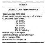
Borbely measured a 2.3ohm output impedance from the circuit. In simulation, it measures 4ohms using 2SK170 model (LSK170 in reality). This seems to give very good bandwidth results using the 2SK180 model.

Obviously this leaves lots to the imagination (bipolar supply, bias supply, etc.) and various V+ supply values need to be reconciled, but I think this is the framework from which I will try to design my amplifier.
Still much to learn, the reading continues...
When I started, I would latch on to a design idea or component and then find a way to implement it, narrows the scope of what needs to be learned. I decided I would like to use a JFET buffer on the input of this theoretical THF-51S common source amplifier inspired by Ben's work. I am also a sucker for things that glow and expensive iron, so a Lundahl choke load on the THF-51S (K&K Audio has taken lots of my hard-earned money). The LL2733 is rated at 0.1H at 3.4A with the coils in parallel, 0.85ohm DC resistance. With 2.5A bias, will be higher than 0.1H in reality, seems a good choice.
I read in great detail Erno Borbely's exquisite article "JFETS: The New Frontier" in which he overviews biasing and basic circuit design, including buffers. From that, and with the input capacitance of the THF-51S in mind, I though his JFET version of the White Cathode Follower was the best pairing.
Borbely measured a 2.3ohm output impedance from the circuit. In simulation, it measures 4ohms using 2SK170 model (LSK170 in reality). This seems to give very good bandwidth results using the 2SK180 model.
Obviously this leaves lots to the imagination (bipolar supply, bias supply, etc.) and various V+ supply values need to be reconciled, but I think this is the framework from which I will try to design my amplifier.
Still much to learn, the reading continues...
Last edited:
The Borbely is close enough at 15V, assuming it is V peak.
Thanks Ben Mah. It looks as though I might have a couple of options for a driver stage as I have been following up on the capabilities of the 2P29L tube preamp I'm building (using the Bartola Mu Follower 'Gyrator' schematic). I am trying to get my head around the maths to calculate the output impedance but I'm told that Zout for the Bartola genre preamps is typically well under the 75ohms you mentioned previously. Maths isn't one of my strengths so it's taking a bit of effort!
Could anyone explain why this circuit does not run away thermally? Some peculiarity of the THF51?
I tried this circuit about 6 months ago with THF51-S but with 25VAC transformer. Never was able to get a stable bias. Maybe the higher voltage (30VAC) is the key or maybe I didn't have the patience 😱
Best
Bob
A note of caution with that setup:
If I remember correctly: with the normal active CCS then there is no real risk of thermal runaway since the overall current is constrained by the upper opto CCS.
With a choke as CCS the lower FET can conduct as much current as it wants with no breaks on thermal runaway. When I experimented with that setup I added a 0.235 ohm source resistor for this reason. If you want the feedback circuit to ignore the source resistor then you can move the 1000 uF cap negative to above the source resitor like the F6 does.
The first circuit, common source with the 2SK180, had issues in my setup. It could be because of the individual SIT. As mentioned above, Bob had a problem with his THF-51S, I had problems with my 2SK180, and OllBoll had issues with his 2SK180. So it does not seem to be just the 2SK180 that has the problem. The THF-51S that I tried did not have the problem.
One possible cause is not enough heat sinking or poor thermal interface between the SIT and the heat sink. I don't believe that was the issue in my case.
An uneducated guess of the cause is the gate leakage current of the SITs. That is a known issue and Michael Rothacher specified a 10K gate resistor to ground that is in series with the bias voltage supply to offset the high gate leakage current in his L'Amp design. What happens is the gate leakage current through the resistor generates a voltage that directly reduces the bias voltage, thereby increasing the SIT's current. In the "bad" SITs the gate leakage current continues to increase as the SIT temperature rises, thereby increasing the voltage drop in the 10K resistor, decreasing the bias voltage some more, and increasing the SIT current some more. An it keeps on cycling.
The 193V choke load used has only 1 Ohm DC resistance so the decrease in Vd due to the increased current is not enough to offset the decrease in Vgs.
Putting in source resistance is one solution. As Iq increases, the source resistor generated voltage adds to the Vgs, keeping Iq in check. The amount of source resistance needed depends on the individual SIT.
Another solution is CCS loading instead of choke loading, where the CCS controls the Iq. Both have their minusses and plusses.
The follower with choke load has the choke on the source side of the SIT. So the current generated by the resistance of the choke adds to the Vgs. The current though the 193V DCR of 1 Ohm provides enough voltage to control the Iq.
Anyways, that is my uneducated guess.
LOrdGwyn,
I like using simulations too, for both trying new circuits and understanding existing circuits. I only started using LTSpice last year and it has been a great educational tool for me.
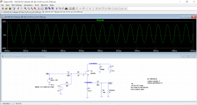
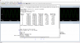
Since I don't have a preamp or voltage gain section built yet that can drive the Fokin to maximum power, I have used a LTSpice simulation to determine maximum power. It is a not a replacement for testing but it gave an estimate. The following shows output of about 23W or 24W at 8 Ohms.
I plan to build a KP926B voltage gain stage once I receive them. however they are still somewhere in transit from Russia. In the meantime I want to do some simulations but unfortunately I cannot find a Spice model for the KP926B. Anyone out there with a model?
I like using simulations too, for both trying new circuits and understanding existing circuits. I only started using LTSpice last year and it has been a great educational tool for me.
Since I don't have a preamp or voltage gain section built yet that can drive the Fokin to maximum power, I have used a LTSpice simulation to determine maximum power. It is a not a replacement for testing but it gave an estimate. The following shows output of about 23W or 24W at 8 Ohms.
I plan to build a KP926B voltage gain stage once I receive them. however they are still somewhere in transit from Russia. In the meantime I want to do some simulations but unfortunately I cannot find a Spice model for the KP926B. Anyone out there with a model?
Attachments

That should be an interesting circuit! I considered buying some KP926B as well, had thought I would like to trace them. My (tube) curve tracer should be able to generate high-voltage, low-current SIT curves, up to 300mA Ids, 700Vds. Depending on how deep this rabbit hole goes I might pursue a tracer for low-voltage, high-current curves, which seems to be the more useful design information, unless transformer coupling like the Nemesis amplifier.
On the tube side of the house, there is a very useful tool made by Dmitry Nizhegorodov that allows one to generate triode models using the characteristic curves, fantastic for me as I can trace some oddball tubes and create my own LTSpice models. I wonder if the same approach could be used for SITs given their triode-like character, perhaps I will ask Dmitry.
On the tube side of the house, there is a very useful tool made by Dmitry Nizhegorodov that allows one to generate triode models using the characteristic curves, fantastic for me as I can trace some oddball tubes and create my own LTSpice models. I wonder if the same approach could be used for SITs given their triode-like character, perhaps I will ask Dmitry.
On the tube side of the house, there is a very useful tool made by Dmitry Nizhegorodov that allows one to generate triode models using the characteristic curves, fantastic for me as I can trace some oddball tubes and create my own LTSpice models. I wonder if the same approach could be used for SITs given their triode-like character, perhaps I will ask Dmitry.
Michael's SIT modeler has been used successfully by several members:
SIT Modeller | AudioMaker
Gate Leakage Current
Gate Leakage Current
After reading Mr. Pass's comment regarding gate leakage current in my Common Drain THF-51S Mu follower thread(Single Ended Tokin SIT THF-51S Common Drain Mu Follower Amplifier , 45W?), I got curious about the actual gate leakage current of the 2SK180s in my amps. As I mentioned in post #194 I thought that it may be a possible cause of runaway issue.
So yesterday I got curious about the gate leak current of the 2SK180s in my 2S180 193V follower amps. First I looked up the Tokin specifications and they specified 100uA maximum at Vgs=-40V.
Mu measurements across 10k resistor at gate to bias supply:
at power up: 15mV
at 1 hour: 200mV (.20V/10k=0.020mA= 20uA gate leakage)
at 3 hours: 900mV (90uA gate leakage) Iq=2.48A
at 5 hours: 1.430V (143uA gate leakage) Iq=2.87A
At this point Iq was drifting up to 2.9A. It had been a while since I last check Iq and it seemed to have drifted so I adjusted it down to 2.8A and the voltage across the resistor dropped to 1.39V (139uA gate leakage). I continued the monitoring and it seemed to stabilize at about 1.3V+/- (130uA gate leakage) across the 10k resistor and Iq=2.75A. There was some drifting due to VAC variations at the wall plug. During monitoring the VAC was fairly high, varying between 121.1VAC and 122.3VAC.
So the measured gate leakage current was very high and in my mind was the probable cause of the stability issue of the amps in common source mode. A 1.43V drop across the resistor in series with the bias voltage reduces the bias voltage by that amount, thereby increasing Iq. In common drain mode, the 1 Ohm DCR of the 193V at the 12SK180 source provides the majority of the bias voltage and tames the runaway Iq. Others have had no issues with their 2SK180s so I think I was just unlucky to get a couple of bad examples.
It's not as uncommon as you might hope unfortunately. Many SissySIT builders ran into this same problem with the R1 build which prompted MZM to pull out the bigger stick to tame them. I had to implement this fix for both channels in my second SissySIT but you won't necessarily know it's a problem unless you let it run for several hours as I was doing with my second build. Trying to fine tune bias/offset for me spanned 4 days because I would adjust it and leave it for 2 or 3 hours and find I had to adjust it again.
As you see in your testing you won't necessarily see the problem even 30 minutes later and also depends how big your heatsinks are because it's positive tempco too.
I won't say if my first SissySIT has this problem because I refuse to measure it so I tell myself I am not seeing a problem there 🙂
Thanks for sharing the finding Ben!
withh Sissy, it can be clever to decrease gate stopper to, say, 22R or so (from prescribed 100R), if you observe sliding ..... this can help a little
SIT gate current was exact reason why I resorted in Singing Bush to bias input JFet buffer, instead of biasing SIT directly
that way, SIT gate current becomes non-issue
same as now is not issue in SissySIT R.3
edit: practically, in Singing Bush - SIT gate is directly connected to current stream of 20mA, with pretty hard defined voltage potential
in SissySIT R.3 , same, current stream being 30mA
Last edited:
- Home
- Amplifiers
- Pass Labs
- 25W Single Ended Hammond 193V Choke Loaded 2SK180 L'Amp