Ah yes I am using the Maplin board which Prasi laid out and I have perfectly matched Hitachi Laterals 1058/162 and struggling to find out the biasing resistor and what bias in voltage term should I set to.
Thanks hopefully others who would have built the same one can chime in.
Thanks hopefully others who would have built the same one can chime in.
Thank you, and I using the board from post . So I need to set it to 100mA bias on the 100R resistor. I usually use the voltage side of the DMM for precise bias, so 100R*100mA = 10mV and I hope I got my calculation right 🙂
Let me do thatA, thanks again.
For 100mA bias, use a 10R-0.5W to 1W resistor, set 1 V across it.
V=IR= 0.1A x 10R=1V
Sorry I misread the thread.
I didnt see it was class A.
Ignore my previous message.
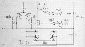
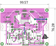
Hello Nigel, its this Maplin amp that manniraj built and attached are the sch and pcb ...
25W Class A amp with Lateral MOSFETs
Attachments
Last edited:
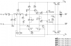
Very simple amp design. Here is the layout i came up with KSA992/KSC1845🙂
For 100mA bias, use a 10R-0.5W to 1W resistor, set 1 V across it.
V=IR= 0.1A x 10R=1V
Thanks Prasi, so basically this version is the class AB version. I will set it to 1V bias using a 10R/2W resistor and hear it once.
Much appreciated.
There is a small concern about the bias, as it appears to be sensitive to
supply voltage. If the DC supply is constant, no issue, but I expect the
voltage across RV1 to drift upwards with supply voltage.
supply voltage. If the DC supply is constant, no issue, but I expect the
voltage across RV1 to drift upwards with supply voltage.
There is a small concern about the bias, as it appears to be sensitive to
supply voltage. If the DC supply is constant, no issue, but I expect the
voltage across RV1 to drift upwards with supply voltage.
Thanks Papa, I am using a 22vac transformer which is giving me a very stable +/-34.5vdc. Able to use RV1 to set the bias without drifting so far. But I am yet to do this setup using the 10R/1-2W resistor as Prasi suggested for 1V bias across this resistor.
🙂
Using a 10R/2W resistor I was able to set the bias to 1V per Prasi suggestion which makes it to 100mA. Played few tracks and its playing beautifully. My small 120/100/50mm heat sink is barely warm even after an hour of playback. Offset is pretty stable around 5-6.7mV.
Thanks all.
Thanks all.
Hello Nigel, its this Maplin amp that manniraj built and attached are the sch and pcb ...
25W Class A amp with Lateral MOSFETs
I did have the right amp after all.
That is the Maplin 75WRMS lateral mosfet power amplifier.
At last found sometime to finish the Maplin and it sounds excellent. Thanks to Prasi for the beautiful layout. I get slight hiss kind of sound which not sure because of my usage currently with closeby AC wiring. I am yet to check with my main speaker setup of Troels 🙂
Few build pics for you Prasi


Few build pics for you Prasi

Hello
I like it, I find this beautifully simple. Single supply, no matching required, no thermal compensation headache. I will build it. I have sources for the parts that I'm hoping are honest (hopefully genuine).
edit: there it is again, that interesting "bootstrap ccs". Looking forward to build this. Thanks Juma
Thanks,
Alex
Hi Skorpio,
I tested your 2-loops idea and it brings some improvement indeed
I also changed the input device into N-JFET which made some other changes necessary and the whole thing now looks like this (and sounds somewhat better) 🙂
Please don't ask me about parts substitutes, power increase or to compare it with other amps/designs....

Last edited:
That circuit is tested and stable. Clumsy prototypes often create problems.
Make reliable connections (PS feedback loops, input, grounding) - no long wires, alligator clips and similar, ground your heatsinks....
100pf on Q4's base and collector is way too much - 10pf or so is more like it.
Try to slightly increase C4 or introduce a couple of pf over R10. Keep gate stoppers (R3, R6, R13, R14) very close to the gates.
I have this amp running on the bench. I used my own pcb design, which I believe is pretty decent.
I have encountered borderline instability.
Differences from the original:
I used J309 instead of J310 (and 2SK170BL)
R1 and R2 are 499K instead of 1M
P1 = 20K (not 10K)
R13 changed to 249R (although this made no apparaent difference)
Removal of the 10pF cap helps, but to ensure stabliity at all signal levels a miller cap of 10pF or greater on Q4 is needed. I have yet to try the suggested cap from Q4 collector to the R8/R9 node.
The amp has some features missing compared to "normal":
- No input filter
- No zobel network
- No output inductor (seems to be unnecessary with cap coupled amps)
Please could you explain a bit more about your design ethos and why these features are not fitted.
Any further comments on the stablity issue?
Those features are ugly, harmful patches (from SQ PoW) but they are mandatory in commercial design and I tend to avoid them when it's possible. Of course, those techniques are well known and anyone can add them to the circuit in accord with specific conditions and needs (this is DIY after all). Stability depends on real-life circumstances too and it's easily achieved/mended once you understand the relations between circuit/components parameters (reactance/impedance ->phase, gain, load...)....could you explain a bit more ...
My "design ethos" (big words if you ask me, but there you have it 🙂) is to make it as simple as possible, fun to build and good enough to listen to Haydn/Mahler through the afternoon without being bored or tired.
Thanks!Those features are ugly, harmful patches (from SQ PoW) but they are mandatory in commercial design and I tend to avoid them when it's possible. Of course, those techniques are well known and anyone can add them to the circuit in accord with specific conditions and needs (this is DIY after all). Stability depends on real-life circumstances too and it's easily achieved/mended once you understand the relations between circuit/components parameters (reactance/impedance ->phase, gain, load...).
My "design ethos" (big words if you ask me, but there you have it 🙂) is to make it as simple as possible, fun to build and good enough to listen to Haydn/Mahler through the afternoon without being bored or tired.
Not sure that I will be doing Haydn/Mahler but looking forward to having a listen.🙂
Sadly I was not able to suppress the oscillation by fitting 20pF from VAS collector to the feedback point (R8/9 node).
The oscillation is about 2V pk-pk in the MHz region and "rides" on top of any output waveform. Both channels are the same.
I have resorted to 20pF miller cap on the VAS to ensure stablity.
May I ask why the J310 was chosen (not another 2SK170)?
Anyway, I will build the cap multiplier PS next and then proceed to audition the amp.
sorry to hear you're having troubles. is the oscillation in single digit (1's of) megahertz or double digit (10's of) megahertz? wondering if the BF862 is screaming or if the output mosfets are or something else entirely ... care to show construction pictures so we can see things like lead dress, grounding, etc.?
also, did you change the gate resistor values at all?
also, did you change the gate resistor values at all?
BTW, with just a quick glance, there are some pretty considerable differences between the J309 / J310 JFETs:

Thanks Mlloyd. I think you might have identifed the reason for the J310 - it provides a couple more volts of VDS for the 2SK170.
That could be a reason for the instability.
OTOH I don't understand how C4 actualy stabilises an amp. It looks to me like it rolls off the gain of the amp at HF which increases the feedback factor and therefore reduces the phase margin... or have I got it wrong?
Moving the end of C4 to the VAS collector effectively misses the o/p stage out of the feedback loop at HF. I can see how that helps phase margin.
I have tried a 249R gate resistor for the 2SK1058. It made no difference.
The oscilation is actually 7V pk-pk at 6.7MHz (sorry I should have been more observant before).
Here is my layout:

Apologies for my typo "Jumo" 🙁
That could be a reason for the instability.
OTOH I don't understand how C4 actualy stabilises an amp. It looks to me like it rolls off the gain of the amp at HF which increases the feedback factor and therefore reduces the phase margin... or have I got it wrong?
Moving the end of C4 to the VAS collector effectively misses the o/p stage out of the feedback loop at HF. I can see how that helps phase margin.
I have tried a 249R gate resistor for the 2SK1058. It made no difference.
The oscilation is actually 7V pk-pk at 6.7MHz (sorry I should have been more observant before).
Here is my layout:
Apologies for my typo "Jumo" 🙁
- Home
- Amplifiers
- Pass Labs
- 25W Class A amp with Lateral MOSFETs