Hey Jason,
I don't know if you caught it or not but in the spice model you sent me you have an MJE350C in Q16. I runs just fine like that and when I changed it out for a MJE15033 There was almost no change. Weird.
I don't know if you caught it or not but in the spice model you sent me you have an MJE350C in Q16. I runs just fine like that and when I changed it out for a MJE15033 There was almost no change. Weird.
That was a mistake on my part. Didn't change the simulation though - still a wicked peak present 😱.
In spice-land transistors don't go 'poof', so you can sometimes make a TO-92 small signal device do Herculean things that would make it instantly explode in real life. An MJE350 would not serve four outputs for long.
In spice-land transistors don't go 'poof', so you can sometimes make a TO-92 small signal device do Herculean things that would make it instantly explode in real life. An MJE350 would not serve four outputs for long.
Yeah, I was just surprised that it worked ok. I'm still interested in making these work if we can. I have quite a few parts invested and I'm hoping to learn something in the process. I am looking at the boards and adding base stoppers would be fairly easy especially if you use SMD's. I looked at the original blameless and it doesn't have base stoppers but of course, it doesn't have multiple outputs. Let's keep looking at this. Maybe there is a way to make a nice amp out of it. We can use my boards as Guinea pigs.
Hi Terry
Yes I agree it would be fairly easy to add some base stoppers to the output transistors if we use 1206 SMT devices. It would require cutting the track and exposing the foil to solder the resistors. The other side could be soldered directly to the pad. There is enough room to give a good result - all that's needed is a steady hand.
I have no doubt that fundamentally it is a good design and might need a few 'tweaks' to get it working.
Hi Terry
Yes I agree it would be fairly easy to add some base stoppers to the output transistors if we use 1206 SMT devices. It would require cutting the track and exposing the foil to solder the resistors. The other side could be soldered directly to the pad. There is enough room to give a good result - all that's needed is a steady hand.
I have no doubt that fundamentally it is a good design and might need a few 'tweaks' to get it working.
I added some base stoppers to the spice model. I also added a trimmer to R4 and it seems to help reducing offset. I'm not sure if this is a proper method but thought I would share. I cant really do anything more with the boards until I get some more transistors so I can at least get the amp working. Then I will look into doing some of the fixes we have been discussing.
Blessings, Terry
Attachments
Hi Guys
C12,8 + R57 form output inclusive comp. You can change it to pure miller by lifitng R57, as the notes say (PDF).
C11+ R56 are in parallel with the feedback resistor. Sometimes you need a high-frequency rolloff there, sometimes not, so the board has these positions.
C19 is something Self recommends to promote high-f stability especially with EF3. It is also something fitted to all Bryston amps.
In my experience I've never needed bas-stops on paralleled output devices - just emitter Rs.
If stability is an issue in sims, I would dump the cascodes as I stated before. The 2N5401/5551 pairs can easily handle the highest rails expected for this amp.
As I said before, DC issues encountered at least as reported by terry are most likely due to solder birdges, microshorts from poor etching, or device damage. I don't recall any oscillation being reported, and unless scoping the output shows something I would not worry about it at this point.
Also as stated, there is absolutely nothing unusual about this design - it is all middle-of the road stuff that's been done thousands of times.
100mV is too much offset. A few mV maybe... I've never built anything tht i could measure the offset of and I don't use servos.
Support: Anyone who emails me gets a response. I don't have a lot of time to spend on forums. Those with so many posts must be retired...
Have fun
Kevin O'Connor
Last edited:
Hi Kevin
I just wanted to say a big thanks for all your time to date in putting together this design, producing the detailed documentation, including Gerbers, and answering questions from beginners like Terry and myself. Very kind of you to donate your spare time that could be spent with your family or other interests. And its a thankless task when things don't go perfectly... 🙂
I'll update you once I've finished stuffing my board and have some results to share.
cheers
Hi Guys
Thanks, Ranchu32.
One diagnostic method that might help determine where the fault on the board lies is to basically turn off the output stage. if you short the bias generator, then further short the bias gen to the output node, you are left with the front-end and VAS as a high-voltage amplifier. In this state, it should provide correct DC conditions and even pass a signal.
Note that the VAS is loaded by the 1k R48 to ground, which will limit the maximum clean output signal when combined with the current limiting in the VAS and CCS.
Another design flexibility is actually afforded by the input stage cascode. The voltage sharing is set by R52,53, which are equal. If one wanted to use a very-high-beta input device that happened to have a low Vce rating, then the ratio of R52,53 can be adjusted to accommodate this, placing more voltage across the cascode devices Q28,29. This might eliminate the sensitivity terry noted above.
Also, although MPSA42/92 and 2N5400/5550 are used as their respective pairs, MPSA92 matches 2N5550 better than any of the other combinations.
Have fun
Kevin O'Connor
Hi all
I'm having dramas sourcing 0R33 5W wirewounds from my local electronics store. Can I assume that the emitter resistor value is non critical and any value between 0R1 and 0R47 would suffice? Both 0R22 and 0R47 are readily available.
Cheers
I'm having dramas sourcing 0R33 5W wirewounds from my local electronics store. Can I assume that the emitter resistor value is non critical and any value between 0R1 and 0R47 would suffice? Both 0R22 and 0R47 are readily available.
Cheers
Hi Guys
Any Re value can be used but you have to adjust the target voltage across the resistor for setting bias. Where 26mV across 330mR causes about 78mA per output pair to flow, the same voltage across 220mR results in 118mA; or 55mA through 470mR.
The actual current is not as important as Vq, according to Self, but it does change the transconductance of the output stage.
Many builders and hobbyists err on the side of higher current to have a larger class-A region. Hopefully the transition point to class-B is high enough in SPL that the distortions caused by that transition will be masked.
Have fun
Kevin O'Connor
Update
Hi all
I thought I'd give an update to keep this thread alive...
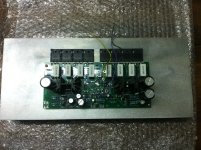
The driver heatsinks I ordered have been on backorder for the past couple of weeks, which has slowed progress. I received these today and should have the first channel completed by the weekend.
The main heatsink you see in the photo Conrad's largest measuring 350x151mm rated 0.21 C/W - one per channel.
I substituted MJE15032/33 for the drivers and KSA1381E/KSC3503E for all TO-126 devices, since these are what I had on hand. I also used Nichicon HE 680u caps where Kevin spec'd 820u devices, since this is what my local supplier had available, and I don't that performance will be dimished too any great extent. Everything else is per the BOM and build notes.
The outputs (MJL21193/94) were hFE matched but I didn't bother matching the other transistors. All transistors were from the same batches and small signal types were taken off the same tape. Point being I haven't gone to any great lengths to minimise offset in the IPS.
Hi all
I thought I'd give an update to keep this thread alive...
The driver heatsinks I ordered have been on backorder for the past couple of weeks, which has slowed progress. I received these today and should have the first channel completed by the weekend.
The main heatsink you see in the photo Conrad's largest measuring 350x151mm rated 0.21 C/W - one per channel.
I substituted MJE15032/33 for the drivers and KSA1381E/KSC3503E for all TO-126 devices, since these are what I had on hand. I also used Nichicon HE 680u caps where Kevin spec'd 820u devices, since this is what my local supplier had available, and I don't that performance will be dimished too any great extent. Everything else is per the BOM and build notes.
The outputs (MJL21193/94) were hFE matched but I didn't bother matching the other transistors. All transistors were from the same batches and small signal types were taken off the same tape. Point being I haven't gone to any great lengths to minimise offset in the IPS.
Attachments
Last edited:
Output inductor
Hi again... any advice on how to form the output inductor?
The build notes state a single layer of 16 AWG magnet wire wrapped around the 1W resistor. Is there a more scientific method for calculating the value and corresponding diameter / turns? I checked the schematic however it doesn't offer any clues.
Use the barrel of a AA battery. About 13mm diameter.
Use enameled copper wire. choose from 1mm to 1.6mm diameter, i.e. whatever you have as stock.
Wind on 8 to 10 Turns all close together.
Slide off the battery and gently stretch so that you can see an air gap between each turn.
Trim the ends to length and scrape the last 4mm of enamel.
Pre-solder these two ends.
Solder into your speaker lead.
Keeping my fingers crossed for you. I hope the KSA/KSC do the trick. I have populate another board but am waiting for some caps to finish it. I know the definition of insanity is to keep doing the same thing, hoping for different results but I was very careful to measure every part and I hFE matched every small transistor. If you get good results I may switch them out. I wrapped my coil around a 10mm shaft. A couple other amps I have built called for that size and I have piece of drive shaft that size. I chuck it in a drill that will turn very slowly. Makes for a nice looking coil. This is the first time I have read someone recommending an air gap between coils. Dr Leach just has you wind a coil tight to the resistor, which is a pretty small coil.
Blessings, Terry
Blessings, Terry
Hi Guys
The TO-126 BJTs can be used for the VAS, current source, bias gen, and predrivers. TO-220s should be used for the drivers.
I blew my wad and got a large quantity of 2SA1381D and 2SC3503D - note both are the same gain range. I was surprised that these are fully encapsulated since the (what I thought were) TO-126s I saw in the past all had a metal back tied to C. It sure makes using them much simpler in many places.
Output coils are ideally air core. It is convenient to wrap the enamelled wire around a 1W resistor, since it is usually helpful to have a resistor in parallel with the coil for high-frequency damping. An air core is preferred to using the resistor form. Andrew and Terry's form ideas are good ones. NEVER wrap the coil around a filter cap.
The specific cap values are higher than what one usually sees, partly to have as much local filtering as possible, and partly because historically local filters have been woefully small. Any design that simply has 100nF caps on the board is asking for trouble.100uF is faaaaar better than the sub-uF value. So, 680 vs 820 is of little concern.
Have fun
Kevin O'Connor
Thanks Andrew, Terry, Kevin.
Kevin, are you suggesting that I should forgo the output resistor altogether if I follow Andrew's or Terry's advice? I was planning to follow Andrew's instructions and wrap 9 turns around the AA battery former and then place the resistor inside, trimming and soldering both coil and resistor into place on the board.
I get the feeling I'm overthinking something that isn't critical... 🙂
Hi Guys
Yes, the output L and R are noncritical values. This is why it can be seemingly crude to say "wrap a few turns" or do it this size or that size as most coils of the range of sizes and shapes that are every used fall into the 2-10uH range required.
The coil is more important to have in the overall output network. The inductance offered by a 100mR wire-wound offers protection from ringing with capacitive loads, too, but adding this much series resistance kills damping and wastes a tonne of power compared to the coil.
Have fun
Kevin O'Connor
i found that ebay have sell mx-1000,pioneer m 90a,sony ta n80es,both of them are similar rms,and same frequency response rated from 20-20khz.but which of them has the better sature,clear clean,high quality build sound?the sony and pioneer seems have the better transformer than the yamaha,but yamaha was the top in audio line?
- Status
- Not open for further replies.
- Home
- Amplifiers
- Solid State
- 250w 8ohm amplifier