Tomorrow is fine with me. It's evening here too. I'm going to look for some tutorials on LTspice and see if I can learn how to use it. Got to be better than wasting components.
Thanks
Thanks
Tomorrow is fine with me. It's evening here too. I'm going to look for some tutorials on LTspice and see if I can learn how to use it. Got to be better than wasting components.
Thanks
Members Keentoken and dadod are "top dawg" "spicers .... look for
their posts and content.
Won't tell you 100% how amps will sound/perform , but sure avoids
the magic smoke scenario's 😀 .
OS
Mission accomplished. I got the spice model up and working and it matches my voltage readings almost to the tee. 2.7V offset. So, now that we know that the circuit is broken, how do we go about fixing it? I will try toying around with the resistor values on the - side and see if I can get it to start producing. Should be fun.
Blessings, Terry
Blessings, Terry
Strange, after making a few corrections to match Struth's schematic my simulation works, sorta... I get about 50mV offset but symmetrical clipping at ~20V. Either way something is horribly wrong. The CCS cascode for the front end seems very wrong. Will poke about some more later. Errands to run.
Strange, after making a few corrections to match Struth's schematic my simulation works, sorta... I get about 50mV offset but symmetrical clipping at ~20V. Either way something is horribly wrong. The CCS cascode for the front end seems very wrong. Will poke about some more later. Errands to run.
Strange, I get 2.7V offset.
I have a couple of questions to hopefully help me understand a little better.
1) If I am shooting for zero offset and 27mv across the .33R emitter resistors, shouldn't I be seeing approximately +-27mv at the output of each output transistor?
2) If the above is true wouldn't I be expecting to see approximately -627mv at the base of the -rail outputs and +627mv at the +rail outputs?
3) How can I get there if I have positive voltage on the -rail outputs?
I am attaching the corrected spice file using the transistors I have in my library. they are a pretty close match to what I used in my amp. Could one of you have a look and see if there are any mistakes compared to Kevin's schematic?
Thanks, Terry
I get 50mV offset.
Run the ".op" command to do your dc bias point calc's sim first.
It is taking a long time to do the transient analysis, but I am getting a sine wave out of it.
Add a 10uH inductor across R47. Zobel before R47, R48 to 8 ohms.
Looked at the FFT, see some small oscillation in the MHz range. No more time to play with it today.
Attachments
Last edited:
Terry,
I have emailed you my .asc file with the models right on the schematic. You should be able to run it that way. My premature clipping issue was pure oversight on my part, Struth notes 10R+Coil but the coil wasn't on the schematic in LTSpice, hence a voltage divider was present 😱.
I have emailed you my .asc file with the models right on the schematic. You should be able to run it that way. My premature clipping issue was pure oversight on my part, Struth notes 10R+Coil but the coil wasn't on the schematic in LTSpice, hence a voltage divider was present 😱.
Hi Jason,
I was able to run the last file you sent me. I seems to run fine. So to test things, I swapped out the transistors in your model with ones from my spice library, and the amp becomes broken again with a big offset. So this is making me wonder if perhaps the transistors I used in my PCB may not be playing well together. They are some I had left over from various builds from 8 or 9 years ago. Maybe I should order some new ones and swap them out and test again. Interesting.
Thanks, Terry
How odd. The devices shouldn't be that critical, any design that is so critically dependant on a specific device or parameter is horribly flawed. Strange how with Cordell's models it runs but with whichever models you have it doesn't run. At least you have an example of a sim that runs to give an idea what you should be getting for various voltages and currents.
OK, I know what was doing it in Spice. I used a Fairchild model for the 2n5401. I think I used Fairchilds on my PCB.. I'm not positive because I had just enough and threw the bag away. Anyway, I will order some new and try those. At least we know that the circuit will work with the proper parts. I'll get some ordered today.
Hi Terry, I'm watching this from the sidelines. I have a board 75% stuffed but it will be another couple weeks until the other parts arrive from overseas.
Please triple-check all the small signal transistors on the board referencing both the silkscreen and schematic (NB: I've found a few omissions in the BOM and I wouldn't rely on it). There are a heap of 2n5401 and 2n5551 parts and I wouldn't be difficult to inadvertently swap a PNP or NPN part.
Please triple-check all the small signal transistors on the board referencing both the silkscreen and schematic (NB: I've found a few omissions in the BOM and I wouldn't rely on it). There are a heap of 2n5401 and 2n5551 parts and I wouldn't be difficult to inadvertently swap a PNP or NPN part.
Yeah, I have been all over the boards several times now. I'm just going to order some new small transistors and swap them all out. In Spice it is Q1 & Q2 that seem to be the most finicky. The others don't seem to care which model I use but 1&2 do care. Just switching from the cordel to the fairchildd will cause the offset to jump over 2 volts. I'll wait for the parts. I have plenty of other projects to work on. I was mainly pushing on this one because I had shared boards with you guys and I wanted to get it working before you had to deal with it. You probably have enough info to have a fair chance at it now.
Blessings, Terry
Blessings, Terry
Hey , this ain't right.
If blokes were having trouble with my "stuff" , I'd be right here with updates,
fixes ...
"support" ??
OS
If blokes were having trouble with my "stuff" , I'd be right here with updates,
fixes ...
"support" ??
OS
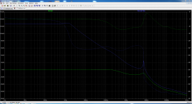
I wouldn't be the least bit surprised if what we really have is a big oscillator, the AC plot looks suspect to me with serious peaking. I'm going to see what altering the compensation values does for this.
Yes , the triple is "wrong" ... look at Cordell's CFA thread statements.
There are TWO lead comp.'s/ FB returns... one from the VAS , the other from the OPS. 😕
The main comp. is a two pole(tmc ??). Poles all over the place.
I did the OLG plot of this ... wow.
I had to backtrack to a simple one cap miller comp.scheme (I made it work)
At this point I was back to a simplified "badger/blameless" topology .
OS
Hi Terry, I'm watching this from the sidelines. I have a board 75% stuffed but it will be another couple weeks until the other parts arrive from overseas.
I'm concerned about stability now that I have been really looking at it. Absolutely none of the usual stability measures for an EF3 have been implemented. The interesting combination and choices in compensation don't adequately bring OLG down enough before we achieve the conditions for oscillation. I looks like it was some kind of exercise in making OLG as high and wide in bandwidth as possible.
I don't go too overboard with placing a ton of trust in the simulations, but I simply don't see how it can be stable. There are simply too many poles adding up. Perhaps in the real world it might work, but I bet it is on the hairy edge of self-destruction and likely very fussy about components and parasitic elements.
Nothing I do to the existing circuit in spice makes me feel comfortable with it. The 7.5MHz-ish peak can be beaten into submission via brute force, but at enormous 'cost' in potential performance.
OS, you have mentioned two lead comps. Look again, we have TMC, shunt and lead. The 22pF from the VAS goes to ground, am I mistaken in calling that 'shunt' or do I misunderstand lead comp in this context?
Sorry Terry, until a set of boards was available I didn't really look at this design all that closely, you know 'blameless' blah blah blah. I poked about a little but clearly not enough. When it came time to actually think about building it (and seeing you having issues) it of course warranted closer inspection and scrutiny.
I'm honestly now not sure if it will be worth the risk in stuffing the boards since the type and quantity of parts for them won't come cheaply, namely the outputs. That said, it might be possible to simplify the circuit a bit and run it as an EF2 output at a lower voltage. Some strategically placed jumpers to 'remove' un-needed parts, etc...
I'm honestly now not sure if it will be worth the risk in stuffing the boards since the type and quantity of parts for them won't come cheaply, namely the outputs. That said, it might be possible to simplify the circuit a bit and run it as an EF2 output at a lower voltage. Some strategically placed jumpers to 'remove' un-needed parts, etc...
Some strategically placed jumpers to 'remove' un-needed parts, etc...
this is doable...
OS, you have mentioned two lead comps. Look again, we have TMC, shunt and lead. The 22pF from the VAS goes to ground, am I mistaken in calling that 'shunt' or do I misunderstand lead comp in this context?
You are right , the 22 pF goes right to earth (HF shunt).
This is a attempt to "force" EF3 stability .Lower Z at HF is what this does.
Instead of making the EF 3 stable beforehand.
If these were the only PCB's on earth , I would eliminate the CCS LTP
cascode, and just fire this amp up with a single CDOM (68-100pf)on the main
VAS .
The lack of basestoppers on the OP devices is a "big one" , as is
not having the driver/pre decoupled.
PS - I would "fix" the triple ... even if you made the IPS stable/workable ... the triple might still oscillate.
So ..... we have both IPS and OPS "shortcomings". 🙁
OS
- Status
- Not open for further replies.
- Home
- Amplifiers
- Solid State
- 250w 8ohm amplifier