Hi all
I've finished assembling the first channel, taking care as I went. I have a +3.68V offset at the speaker output - similar to the problem Terry reported a few pages ago.
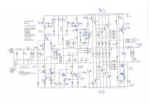
I've triple checked everything and can't spot any obvious problems. Any assistance appreciated. See attached schematic with voltage overlay.
I've finished assembling the first channel, taking care as I went. I have a +3.68V offset at the speaker output - similar to the problem Terry reported a few pages ago.
I've triple checked everything and can't spot any obvious problems. Any assistance appreciated. See attached schematic with voltage overlay.
Attachments
Try removing the diodes 'protecting' C4, or replace C4 with a lower value higher voltage part. You have some current flowing through R15 (the 1K in the FB leg) that should be virtually nil.
Last edited:
Thanks very much Jason. I cut these diodes and my offset has now settled into sub ~10mV at the output 🙂
I have a 2.2mF 16V electro in C4. Should I be concerned that its not a polarized cap?
I have a 2.2mF 16V electro in C4. Should I be concerned that its not a polarized cap?
i suspected this much in my previous post....the diodes made the amp "dc coupled" as far as the feedback network is concerned....
if that were my amp, i'd do away with 4 diodes across C4, and get a non polar cap for C4........
the voltages on the bases of Q13/14 should be closely the same at about + and - 1.5v
wrong value resistor in the biasing of the CCS and VAS could be the cause....
also look out for the vbe ref Q11 make sure it is connected tight....
Thanks very much Jason. I cut these diodes and my offset has now settled into sub ~10mV at the output 🙂
I have a 2.2mF 16V electro in C4. Should I be concerned that its not a polarized cap?
C4 is a polarized cap, but it is so large in capacity that I suspect that during power-up any 'transient' that occurs causes the diodes to begin conducting and they stay that way which prevents it from 'settling' inducing an offset.
D1 and D2 can be retained in circuit, D3/D4 steals current from
the base of Q2 because it is forward biased, so it looks more like
the cause of the offset voltage at output....
C4 can be 47ufd corner frequency is still about 4 hz...
the base of Q2 because it is forward biased, so it looks more like
the cause of the offset voltage at output....
C4 can be 47ufd corner frequency is still about 4 hz...
I am a little puzzled that this NFB cap has been specified so large (i.e. 2.2 - 4.7mF) when most examples I've seen are an order-of-magnitude less (Self's sample schematic shows a 220uF cap with a single protection diode.
I discussed with Andrew earlier in this thread and he advised the minimum value for this design to be 146uF (and provided the calculation to prove it). I can't find any examples where such a large NFB capacitor is specified and wonder about Kevin's motivations for including it (and the drawbacks).
At this point I've got a few thoughts:
- Assume having a polarised NFB electro without protection diode is a bad idea.
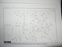
- Could try fitting a single protection diode across the existing cap per Self's example attached and see if that keeps leakage current under control
- If not substitute a 220uF polarised per the diagram.
- Alternatively, remove the 2.2mF electro, properly reform it then reinsert in the PCB and reinstate the zener protection network. If the diodes are conducting as a result of leakage current then this may solve the problem. But what if I power up the amp after a year or two in storage? I don't want to have to reform the cap every time.
- Bi-polar caps are pretty bulky and I won't be able to fit a very large one in the available footprint. Is it necessary to use a bipolar?
I discussed with Andrew earlier in this thread and he advised the minimum value for this design to be 146uF (and provided the calculation to prove it). I can't find any examples where such a large NFB capacitor is specified and wonder about Kevin's motivations for including it (and the drawbacks).
At this point I've got a few thoughts:
- Assume having a polarised NFB electro without protection diode is a bad idea.
- Could try fitting a single protection diode across the existing cap per Self's example attached and see if that keeps leakage current under control
- If not substitute a 220uF polarised per the diagram.
- Alternatively, remove the 2.2mF electro, properly reform it then reinsert in the PCB and reinstate the zener protection network. If the diodes are conducting as a result of leakage current then this may solve the problem. But what if I power up the amp after a year or two in storage? I don't want to have to reform the cap every time.
- Bi-polar caps are pretty bulky and I won't be able to fit a very large one in the available footprint. Is it necessary to use a bipolar?
Attachments
notice that the diode is reverse biased wrt the ltp input trannie....
tbh, i never used any protection diodes for caps in any of my builds....
tbh, i never used any protection diodes for caps in any of my builds....
The FB cap is only subject to significant voltage under fault conditions, so for the most part the diodes aren't required. If a fault that puts a rail at the output occurs you likely have bigger issues than a capacitor going pop.
I think Struth's notion was to take the 'required' corner frequency, which is generally considered to be a decade away from the audible limit, and move it again by an order of magnitude. This is to make the signal voltage on the capacitor negligible and therefore its effect on the sound and distortion negligible. I believe D. Self wrote about this.
I think Struth's notion was to take the 'required' corner frequency, which is generally considered to be a decade away from the audible limit, and move it again by an order of magnitude. This is to make the signal voltage on the capacitor negligible and therefore its effect on the sound and distortion negligible. I believe D. Self wrote about this.
a very big cap for C4 makes recovery from overloads very much delayed...
during which time, the amp can run tantrums.....😀
the one thing i learned from this board and what the gurus here have said,
"use only enough capacitance as necessary"
during which time, the amp can run tantrums.....😀
the one thing i learned from this board and what the gurus here have said,
"use only enough capacitance as necessary"
so now, Terry can finish his amp....
Well it might be a bit premature to claim victory. I removed the safety resistors on the rails and now the outputs are overheating... Hot enough to warm up a 0.25C/W heatsink in a few seconds but not enough to blow the 5A fuses.
So I'll have to investigate further when I have some more spare time. When I do I'll remove the 2.2mF NFB cap and install a 220uF cap in its place.
Thanks everyone for your advice.
If you have a scope, look for oscillations too. That is often the cause of mysterious rapid heating. The typical precautions against oscillation haven't been taken in this design and some combinations of devices could oscillate. I had to apply some countermeasures in the simulation of this amplifier to keep it from oscillating and give it some phase margin. I wouldn't be surprised if some of the stability issues in LTSpice exist in real life.
Just remember, I have not built my set of boards and likely won't. I'll save the parts for something else. If someone wants to pay postage I'll make my set available.
Just remember, I have not built my set of boards and likely won't. I'll save the parts for something else. If someone wants to pay postage I'll make my set available.
yes, that is possible since no base stoppers were used at the output,
2.7 to 4.7 ohm in series with the output trannie bases will take care of that,
be prepared to replace that 1k bias pot with something bigger, say 2k or else change R28 to something like 2.2k
2.7 to 4.7 ohm in series with the output trannie bases will take care of that,
be prepared to replace that 1k bias pot with something bigger, say 2k or else change R28 to something like 2.2k
Unfortunately I don't have a working scope but I suspect it is oscillating: -
With the trimpot "all in" and on cold power up the output offset quickly settles to ~10mV. Voltages and temperatures remain stable even after 10 minutes or so. I don't get any signs of oscillation when probing the speaker out terminal.
But as soon as I probe an output emitter resistors (using the pads marked M1 & M2 on the schematic) to start dialing in the bias, the output offset becomes erratic and the output transistors quickly overheat. Interestingly, the drivers, pre-drivers and VAS remain perfectly cold throughout.
Does this sound symptomatic of oscillation in the OPS?
- Status
- Not open for further replies.
- Home
- Amplifiers
- Solid State
- 250w 8ohm amplifier