I have designed these analog soft-start,protection circuits and can offer them to you. Basically they are deriviatives of old Pioneer designs as found in SX-x50 series receivers or Spec series PAmps. You can get these service manuals from hifiengine.com. Use modern day Fairchild bjts.
Rick
Rick
Really? That would be great. I don't have much more work to do to mine so i'll post them as soon as possible.
Power Entry with soft-start relay that is run off the unregulated +ve supply.
Attachments
Last edited:
Try again, works for me when I download in Firefox and do a quick view. Maybe because I was editing and uploading the top assembly drawing.
My android adobe reader fails to open the files. I'll check tomorrow morning on the pc. Thanks for the schematics!
Also, do you have an android tablet? If so i can provide you with the schematic drawn and simulated in everycircuit. It works like a charm.
Also, do you have an android tablet? If so i can provide you with the schematic drawn and simulated in everycircuit. It works like a charm.
Sorry, I am old school 🙂 Now that I know the android will not open a simple pdf file, looks like I would never want one.do you have an android tablet?
Android is an extremely powerfull platform. It usually works flawlessly; yet i have shi**y wireless coverage on my room and this is most likely the reason why the download gets corrupted.
Hey.
Not sure if troll or just mistakingly posting in another thread.
Anyway, i'd go for spec-2. I haven't listened to any, but from what i've read on the web, spec-2 has some kind of sweet sound, while thr m91 has a hardh sound with bloated bass and somehow distorted mids.
I suggest you open a thread for this in the correct category and please, write more clearly and no caps.
Have a good day sir!
Hi Brlmat,
Did you ever build the Blameless? Since we talked here I built the DX Blame MKIII, Honey Badger and DX Super A. They all sound good and are all very similar in sound. The Honey Badger has +/- 67V rails, the MKIII +/-77vdc rails and the Super A +/-37vdc. There is almost no discernible difference. I think I am going to stick to lower voltage from now on. The extra weight and cost is not worth the efforts.
Blessings, Terry
 all caps post removed, please do not post in all caps....
No, Terry i haven't yet. I bought the project from Kevin's website and it looks awesome. I've been really short on money lately, but will certainly build it.
Hi Guys
Terry wrote: " I think I am going to stick to lower voltage from now on. The extra weight and cost is not worth the efforts."
That's me, too!
There are technical advantages to high voltages and to the use of many paralleled output devices, but you can get phenomenal performance with a single pair at low voltages. As I've reported here and elsewhere, in my own listening environment I don't really need more than 1W in total split between the two subs and two sats - it's a 2.2 system.
Save your hearing as well as your back... and wallet.
Terry, you're a busy guy! For me, I don't have the time or space to have multiple systems, so building hifi stuff for myself has an "end game" of actually using it - hopefully forever.
I hope you power all of your amps regularly to keep the electrolytics healthy. They become temperamental with disuse.
Have fun
Kevin O'Connor
Hi Guys
Brlmat wrote: "The thing is that i have the 1 sec softstart which i wouldn't do with a RC timer as it doesn't always get discharged fast enough in case of power cycling. I also need the 5 sec timer for power on mute which again, would only work properly with something other than a RC timer. I thought of using a 555 timer but i have yet to unravel the ways it can be set up."
The key here is to monitor the AC voltage from the PT. You can use it for a fast-off of any TOC circuit.
Have fun
Kevin O'Connor
Hey Kevin,
Yeah I have a pretty tall stack of amps now. I try to listen to one or two different amps each day so they each gt heated up every couple weeks. Speaking of less is more, I just finished a couple VVSA's. One had TO-3 outputs and the other semilab. These have only 6 transistors each and the sound is quite surprising. Lot's of interesting designs out there. 😀
Good to see you back around.
Blessings, Terry
Hi Guys,
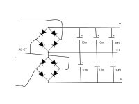
I had some boards made from Kevin's Gerbers. Just waiting on a few parts so I can finish it. I'm planning to use an old Soundcraftsmen transformer that is 67-0-67vac. The transformer has a center tap but my supply board has two bridges and was designed to hook to twin secondaries. I just plan to connect to CT to one side of each bridge. My question is does it matter which side of each bridge the CT connects to? I am attaching crummy drawing that I made to illustrate my question.
Thanks, Terry
Attachments
imho, you are better off with just a single bridge, double bridges are meant for 2 separate windings,
Hi Guys
Terry, AJT is correct.
You should modify the bridge connection and use just one, tying the CT to the caps via the appropriate unused bridge pad.
Have fun
Kevin O'Connor
Terry, AJT is correct.
You should modify the bridge connection and use just one, tying the CT to the caps via the appropriate unused bridge pad.
Have fun
Kevin O'Connor
Hi Terry
This diagram doesn't look right to me:
- The V+ pick up point should be at the intersection between the two diode cathodes.
- The V- pick up point should be at the intersection between the two diode anodes.
- The ground plane is connected to the top bridge rectifier where the two anodes intersect, and to the bottom bridge rectifier where the two cathodes intersect.
- Do not directly connect the ground plane to the CT
- Connect one of the transformer secondary wires to the top bridge rectifier AC input and the other secondary wire to the bottom bridge rectifier AC input.
- Join the remaining AC input on each bridge rectifier.
I agree with AJT, but that wasn't your question.
i gave him an option, up to him to take it or leave it.....it's not my amp....
i would know what to do on my amp.....
i would know what to do on my amp.....
- Status
- Not open for further replies.
- Home
- Amplifiers
- Solid State
- 250w 8ohm amplifier