With connection like in post 396 You make short circuit across two diodes
Thanks, you caused me to go back and look at my drawing a little closer. I see it now. That explains why I had more voltage on one rail than the other too.
Terry wire your psu bridge diodes like this..place both diode units side by side...and parallel wire both ac input points together on the bridge diode unit and wire your secondary wires from the transformer to the ac points connections on the diode bridge unit..now add parallel wires from plus to plus + +...and the same with the negative tab connections. then take your feeds to the filter caps in the same way just like wiring a normal b-unit.
Hi Amptech,
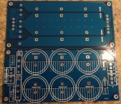
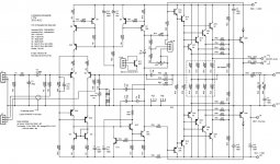
I actually was not set on using two bridges per se. The PSU boards are set up that way. One bridge feeds the + rail and the other feeds the - rail. Seems to work fine when using a transformer with dual windings. I just removed the dual bridges and jumpered where the bridges were and put a standard 35A bridge in front. You can see in the attached.
Blessings, Terry
Attachments

Hi Struth et al.
Terry is kindly sending me a couple of his boards and I downloaded your parts list and notes several months ago - so ideas are starting to float around in my head 🙂
I'm considering a SMPS instead of big iron & copper for this build, since there is limited availability of high power and high voltage transformers here down under. The only options seem to be custom wound or importing from overseas and both options are rather expensive - the latter due to shipping costs.
In particular, I'm looking at the range here at Connexelectronic (Connexelectronic). Perhaps two of the SMPS500R, custom wound for 90VDC rails (dual mono), or perhaps the SMPS2000 instead.
I'm terms of PSU pros/cons, I assume your design is like most other Class B amplifiers, with this one having an unusually high PSRR. Do you have an opinion on this?
cheers
Hi Christian,
I read through Kevin's notes last night. It looks as though this amp will work very nicely on lower rails. If it is anything like the other Linn/Blameless amps I've built, it won't be fussy about the power supply. I had wondered about running SMPS in series. Ebay carries a nice little +-25vdc SMPS. I just got one and tried it out on my JLH 1969 and it didn't break a sweat running both channels off one rail.
110V 220V 200W Digital Amplifier Power Supply Board with Switching | eBay
To be honest I don't understand why Struth specified 90V rails for this 250W amp. By my calcs 67V is the minimum for 250W into 8R - a big difference. I've got a 50V-0-50V toroid that would give nearly bang on those rail voltages.
You would have to read back through this thread. It had to do with the OP's needs. I am only doing it because I happen to have a transformer that puts out that much. I used a 55-0-55 for my DX MKIII and a Hafler P230 transformer for my Honey Badger. I think it is ±76Vdc. I am only doing it to make use of the one I have.
Blessings, Terry
Blessings, Terry
Ranchu is right.To be honest I don't understand why Struth specified 90V rails for this 250W amp. By my calcs 67V is the minimum for 250W into 8R ..........
250W into 8ohms is equivalent to 63.2Vpk at the output when the load is connected.
A PSU that sits at +-90Vdc when idling and yet only allows 250W into 8r0 is seriously flawed.
I would expect +-71Vdc to hit the 250W into 8r0 target.
Kevin didn't say this amp would only hit 250W. Have you guys read through the thread? I don't have time to search back through to find the answers for you, but I have followed the thread from the beginning. To be honest, I don't think Kevin even encourages this high of rails, he was just trying to help out Brlmat. As I already said, I am using it because I have the transformer and this amp gives me a chance to utilize it. My Leach Superamp is running on about the same rails.
The amps I listen to most run on 37V rails and are probably running at 5 watts at listening level. I will crank it up once in a while just for kicks but most of the time they are just cruising.
The amps I listen to most run on 37V rails and are probably running at 5 watts at listening level. I will crank it up once in a while just for kicks but most of the time they are just cruising.
Hi Terry
I've been following this thread since the start but my memory of what was discussed months ago is not so good. I'm particularly referring to the notes ("LTT4-note.pdf") that came with the Gerbers where it clearly states "250W - 8R with +/-80V to 90V supplies" in the heading, and then in the document goes on to talk about 90V rails.
On the one hand I'm unconcerned because this circuit can be easily adapted to suit a wide range of voltages. But it would be good to know whether the feedback resistor values were specified to suit the specified power target or specified rail voltage (it can't be both since they're contradictory). That way I can scale these resistor values up or down to to tweak the gain to suit my transformer.
80V and 90V rails should yield approx. 350W and 450W, respectively, into 8R assuming stiff supplies and typical losses in the amplifier itself.
To be honest I don't understand why Struth specified 90V rails for this 250W amp. By my calcs 67V is the minimum for 250W into 8R - a big difference. I've got a 50V-0-50V toroid that would give nearly bang on those rail voltages.
in case of voltage regulation of transformer is such that rails drop to about 70 volts at full power....
the Pioneer Spec2 starts out with 90 volts no unloaded and ended up with 71 volts at full power as show in their schematics..
i also use a 50-0-50 ac transformer for my super leach....
so using a smps psu, 65 to 70 volts seems just about right...
if you are just listening to music and doing an FTC test, then that is fine...
smps
You should be able to purchase an smps from here vicol audio : high-end amplifiers & audio tuning
You should be able to purchase an smps from here vicol audio : high-end amplifiers & audio tuning
Thanks AJT, I'm going to utilise a 50V-0-50V transformer I have on hand for this project, which should prove more than adequate for the power levels I require.
I'll pursue the SMPS for a lower power and more familiar amplifier design.
I'll pursue the SMPS for a lower power and more familiar amplifier design.
Hi guys... I've received a couple of boards from Terry and started stuffing them with parts I had on hand.
There is a small error on the silkscreen that I'd like to point out:
R13 should be 2k21 (not 1k0)
There is a small error on the silkscreen that I'd like to point out:
R13 should be 2k21 (not 1k0)
Good catch Christian. I hadn't noticed that. I just checked and I have 2k21 in there so I must have been installing from the BOM.
Blessings, Terry
Blessings, Terry
OK, I seem to have found another issue. My boards won't power up correctly. While searching for the problem, I discovered that the pinout for J11-B does not match the schematic. On the schematic, Pin#1, the collector for Q11, goes to the junction of R14/R29, which it does on the board as well. On the schematic, pin #2, the base of Q11 goes to the junction of R13/R28 only, and pin #3 goes to the sweep and one side of R27 then continues on. On the board, Pins 2 and 3 are connected and hit R13/R28, and only one side of R27 and then continue on. The sweep and other side of R27 are shorted and hit the other side of R28. I am showing the real circuit in the small cut below. I'm not sure how this affects the circuit, but I know mine is not working right so I am asking you guys who understand this better to give it a look. The pic showing the bottom foil is mirrored to reflect how it would look from the top. I
Thanks, Terry
Thanks, Terry
Attachments
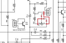
Terry, I checked checked over one of my boards and see what you mean. The schematic is correct, the board layout is not. Fortunately it should be an easily fix by cutting a couple of tracks and adding a wire link to connect the wiper to the pin marked "0" on the schematic.
Yeah, I know I can change the board, I just wasn't sure if it was necessary. I sent an email to Kevin to ask if he had changed the layout on purpose and just forgot to change the schematic. It would be nice to find out that I didn't make an error on the boards. I tried to be careful when stuffing them. I was actually surprised when they didn't work right off. After measuring voltages it just seemed to point to Q11. That is when I realized that the pinout didn't match the silkscreen. Hopefully Kevin will pop in in the next couple of days and give some direction. I don't want to just start cutting if he has a better solution. This is why initially I had planned to hold the boards until I got them working. However, you guys know more about circuitry than I do so you are probably better at troubleshooting than me.
Blessings, Terry
Blessings, Terry
- Status
- Not open for further replies.
- Home
- Amplifiers
- Solid State
- 250w 8ohm amplifier