Clipped said:
i changed those zeners out with fresh ones, replaced the tantulum with same value, and put in a 1/2 watt 3 ohm resistor, in place of the bad one.
the current is down to normal now after changing those fets.
with resistor in place:
1.25vdc/ 1.1ohm = 1.13 amps
(with the resistor removed it also looks normal now)
it shut down because i tested it without the resistor with music.
(i'll admit it) prior to changing them the current was excessive.
-------------------------------------------------------------------
the sound was scratchy so i changed the pot, but too 100k, since this was all i had, other than 250k and 10k...will i be losing volume because of this 100k?
right now i have 3 different fets in the ps ..
15= smp60n06
2=IRFZ44n
1=ssp60n06
i will change them once this thing is debugged.
one strange thing, the fets on the yellow side run cooler than the other bank.
anything i should check out before i take the resistor off the B+ and test it full tilt?
im listening to it right now with power resistor in place bridged mono @4 ohms...for around 40 minutes now.
so , i guess everything is good to go?

im going to change all the ps fets today, so i'll let you know if there's an explosion.
The pot is in the feedback circuit so higher resistance will increase the gain.
Are all of the FETs new (never in the amp when the power supply failed)?
If all of the SMP60N06s are new, I'd suggest running 7+7. If they get hotter on one side than the other, check the A06/A56 drivers in the PS. Are the gate and drain waveforms the same on both banks?
Check the waveforms at ~12.5 v and at ~13.8v (or wherever the regulation drops the gate drive voltage).
Have you checked EACH of the gate resistors INDIVIDUALLY?
What are you using for drivers in the audio section?
just got some new pots today, will be putting back in the 50k
--------------------------
the fets that were in the ps, when it failed were, smp60n06 from various amps i pulled them from...but all metered correctly.
i just went and bought some IRFZ48n fets to put in, these were the closest ones i could find around here.
--------------------------
i was suspecting the a56/06 like you said , i metered them in board but havent had time to pull them out and check yet.
-------------------------
cant check the waveform, no scope. 🙁
--------------------------
ive checked the gate resistors but didnt pull the legs...im going to go ahead and change them out when i put in the new fets.
--------------------------
for the drivers and pre drivers...im using mangled 2NE6488/91...with the legs bent around.
---------------------------------------------------
for the actual output,i just bought some BD909/910 (80volt)im going to replace the 6488/91 with....i usually use BD911/912 (100volt)so it runs cooler, but i believe that the 909/910 are stronger with the given rail voltage, or i may be wrong....we'll see.
they are both 90 watt devices opposed to the 2n6488/91 which are 75 watts. all three have the same current rating.
working on these orion amps are hell, so many transistors/fets/resistors...
--------------------------
the fets that were in the ps, when it failed were, smp60n06 from various amps i pulled them from...but all metered correctly.
i just went and bought some IRFZ48n fets to put in, these were the closest ones i could find around here.
--------------------------
i was suspecting the a56/06 like you said , i metered them in board but havent had time to pull them out and check yet.
-------------------------
cant check the waveform, no scope. 🙁
--------------------------
ive checked the gate resistors but didnt pull the legs...im going to go ahead and change them out when i put in the new fets.
--------------------------
for the drivers and pre drivers...im using mangled 2NE6488/91...with the legs bent around.
---------------------------------------------------
for the actual output,i just bought some BD909/910 (80volt)im going to replace the 6488/91 with....i usually use BD911/912 (100volt)so it runs cooler, but i believe that the 909/910 are stronger with the given rail voltage, or i may be wrong....we'll see.
they are both 90 watt devices opposed to the 2n6488/91 which are 75 watts. all three have the same current rating.
working on these orion amps are hell, so many transistors/fets/resistors...
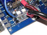
Im not sure if the other tech put the A56/06 drivers in the right place...could you take a look at this pic and verify?
thanx
thanx
An externally hosted image should be here but it was not working when we last tested it.
jeez....man, what the ...oh gawdddd...
there is no resistor there for the a56 on the yellow side...
the one on the orange side is 10 ohm....yellow side the same value?
i must find the previous tech and smack him upside the head, just once.... 😡
man, i just want to say thank you for all your help, this amp has been disected ,mutilated and dismembered...theres no way i couldve gotten this thing working without your help.
btw, theres two filled in vias by the screw hole next to the last fet on the yellow side, it doesnt look like anything is supposed to go there...but just incase....is there supposed to be?
The resistors are the same on both sides.
Those vias are empty (no electronic components).
After you've got it working, you should go back and clean all of the flux from the solder conections with acetone and a toothbrush. If you haven't been doing this, it has to be a mess from all the times you had to pull the various parts.
Be sure to discharge the B+ caps (by shorting the power/ground wires together) before cleaning the board. Clean the board outdoors. Acetone is extremely flammable.
well i dont think i was meant to get this amp working....after i put that 10 ohm resistor in ,the new fets, new a56/06 drivers and new gate resistors...everything went downhill from there.
i powered it up through the resistor and output was way distorted and the volume level dropped to about 20%
shut it down to check things out and the next time i turned it on, a diode blew (the one on the orange side to the right side of the vertical standing 6488)
changed that diode, as well as the the teardrop tantulums in the ps.....changed the vertical 6488 and replaced the L7815 reg.
now it wont even power up...
i powered it up through the resistor and output was way distorted and the volume level dropped to about 20%
shut it down to check things out and the next time i turned it on, a diode blew
(the one on the orange side to the right side of the vertical standing 6488)changed that diode, as well as the the teardrop tantulums in the ps.....changed the vertical 6488 and replaced the L7815 reg.
now it wont even power up...
Is it possible that you have a solder bridge between the terminals of one of the components you replaced?
Double-check with your ohm meter to be sure that there are no shorted connections.
Double-check with your ohm meter to be sure that there are no shorted connections.
ive checked and double checked im not even getting any voltage at pins 8,11, 12 in the tl494.
legs 4 and 5 on the mct2 dont have any voltage either. ...but leg 1 gets 1.23 vdc
im also trying to trace back where the thermostat is getting power from, but having a hard time following it back.
but im finding something weird though... there are two diodes that appear to be backwards, i dont know if this is the way its supposed to be or not because when i look up pics on the web, they are the opposite of the orientation of this amp, maybe people trying to fix this amp put them in backwards...its questionable.
this is how they are:
but when i reverse them and put them in the correct '''traditional position'''.... the one on the bottom burns up.....if i leave them the way they are nothing happens.....it stays
the diode on the bottom did burn up in this position before i changed it...but after replacing it in the same position, it has stayed.
the amp played the other day i was testing it, all day...i put a heat sink on my powerline resistor in case your wondering.
legs 4 and 5 on the mct2 dont have any voltage either. ...but leg 1 gets 1.23 vdc
im also trying to trace back where the thermostat is getting power from, but having a hard time following it back.
but im finding something weird though... there are two diodes that appear to be backwards, i dont know if this is the way its supposed to be or not because when i look up pics on the web, they are the opposite of the orientation of this amp, maybe people trying to fix this amp put them in backwards...its questionable.
this is how they are:
An externally hosted image should be here but it was not working when we last tested it.
but when i reverse them and put them in the correct '''traditional position'''.... the one on the bottom burns up.....if i leave them the way they are nothing happens.....it stays
the diode on the bottom did burn up in this position before i changed it...but after replacing it in the same position, it has stayed.
the amp played the other day i was testing it, all day...i put a heat sink on my powerline resistor in case your wondering.
is that a 7915 in that pic, because theres a 7815 in this one.
the diodes in this amp are facing in the opposite direction.
***scratches head***
the diodes in this amp are facing in the opposite direction.
***scratches head***
when i put the diodes in the correct orientation the bottom one burns up, tried 4003 4004 4005 just incase the other guy put in the wrong value, but it still burns and smokes...
this amp is one messed up piece of equipment.
this amp is one messed up piece of equipment.
The bottom diode feeds B+ to the MPSA06.
If the diode is burning up, I'd think that there would be a short circuit to ground somewhere.
The MPSA06 can't handle as much current as the diode so I'd expect it to be damaged also.
If the diode is burning up, I'd think that there would be a short circuit to ground somewhere.
The MPSA06 can't handle as much current as the diode so I'd expect it to be damaged also.
the area with the dides and 7815 looks pretty messy, im gonna scrape off the solder mask to look for cracks in the board and clean things up to get a better look.
in this area it looks kinda charred with a couple fiberglass strands starting to poke through.
legs 4,5,6 of the mct2 measure ok, anyway to measure legs 1&2?
should it be open or should i get some type of resistance reading?
but man, how was it that this amp stillworked even with those diodes in backwards.... 😕
i guess that 10 ohm resistor in the yellow side ps was taken out to avoid this mess, and jump start it....but now even after i try taking it back out, it still dont work.
(and i thought i was almost finished)
in this area it looks kinda charred with a couple fiberglass strands starting to poke through.
legs 4,5,6 of the mct2 measure ok, anyway to measure legs 1&2?
should it be open or should i get some type of resistance reading?
but man, how was it that this amp stillworked even with those diodes in backwards.... 😕
i guess that 10 ohm resistor in the yellow side ps was taken out to avoid this mess, and jump start it....but now even after i try taking it back out, it still dont work.
(and i thought i was almost finished
)I don't think the amp could have powered up with the bottom diode reversed unless it was shorted.
The other diode isn't as important. It can probably be left out untill you get the amp to power up.
Legs 1 and 2 of the opto-coupler are the LED. You should get a reading of ~1.25 volts (which you already read a few posts back).
With the bottom diode in correctly and the amp powered up, what's the DC voltage on the 3 legs of the MPSA06 (black lead on ground)?
If the bottom diode is still failing when in correctly, pull the A06 near the opto-coupler. Does the diode still get hot/fail?
The 10 ohm resistor should not have had an effect on this part of the circuit. It could have made the FETs run hot but it couldn't have caused these problems.
This is starting to seem like a test of some sort. I don't know if you're testing us or someone's testing you. 🙂
i feel the same way man....test....to top it off, the head on my soldering iron has just officially wore out, im gonna take a couple days off from this amp before i go nuts.
maybe this is a sign by the amplifiers gods to sacrifice a pyramid amp.
maybe this is a sign by the amplifiers gods to sacrifice a pyramid amp.
ok man, i got everything back together , cleaned the board up a little by the vertical 6488...
powered it up and its back to life....the diode is not burning out...but i currently have a 4005 in there.
the teardrop tantulum by the A06 was bad, i dont know when it went bad, because i changed it....anyway, changed it again.
music plays through it..but,but,but....the output is low and distorts at low volumes...and your going to love this....rail voltage is only 18vdc...
that A06 you asked me to measure is:
e=10.78
b=11.39
c=11.59
18 volts for the rail....and the fets on the orange side still get hotter than the yellow side...that vertical 6488 seems to be getting hotter than it should be...
you asked me before to use a scope to look at the waveform...i dont have a scope, but if it helps...my meter can measure frequency...
if i ever get this thing working properly, im going too be afraid to put it in my car...
continued from above post:
-----------------------------------------------
the fets in the ps measure as following for both sides:
pin 1= -1.86 vdc
pin2= 12.3 vdc
pin3= 0.001 vdc
----------------------------------------------
frequency :
pin 1/both sides = 19.85 khz@VDC
pin 2 orange = 62 to 63 khz @VAC
yellow = 57 to 58 khz @VAC
no frequency comes up for VDC
-----------------------------------------------
vertical 6488
pin 1 = 0.539 vdc
pin 2 = 3.6 vdc
pin 3 = 0.001 vdc
L7815
pin 1 = 9.66 vdc
pin 2 = 0.001 vdc
pin 3 = 8.72 vdc
----------------------------------------------
rectifying diode on orange side:
pin 1 = 4.87 vdc
pin 2 = 0.001 vdc (dont forget LOL)
pin 3 = 4.81 vdc
rectifying diode on yellow side:
pin 1 = 4.78 vdc
pin 2 = 9.69 vdc
pin 3 = 4.73 vdc
---------------------------------------------
and it gets weirder
if i measure the secondaries i get 13.8vac, with one lead on one of the center legs and the other on one of the two outer legs.
if i put each lead on an outer leg i get 27.5 vac...
but the rail voltage is +/- 18vdc ....wtf?
18 volt rail voltage isnt because of the inline power resistor is it?
because now im afraid to take it out.
-----------------------------------------------
the fets in the ps measure as following for both sides:
pin 1= -1.86 vdc
pin2= 12.3 vdc
pin3= 0.001 vdc
----------------------------------------------
frequency :
pin 1/both sides = 19.85 khz@VDC
pin 2 orange = 62 to 63 khz @VAC
yellow = 57 to 58 khz @VAC
no frequency comes up for VDC
-----------------------------------------------
vertical 6488
pin 1 = 0.539 vdc
pin 2 = 3.6 vdc
pin 3 = 0.001 vdc
L7815
pin 1 = 9.66 vdc
pin 2 = 0.001 vdc
pin 3 = 8.72 vdc
----------------------------------------------
rectifying diode on orange side:
pin 1 = 4.87 vdc
pin 2 = 0.001 vdc (dont forget LOL)
pin 3 = 4.81 vdc
rectifying diode on yellow side:
pin 1 = 4.78 vdc
pin 2 = 9.69 vdc
pin 3 = 4.73 vdc
---------------------------------------------
and it gets weirder
if i measure the secondaries i get 13.8vac, with one lead on one of the center legs and the other on one of the two outer legs.
if i put each lead on an outer leg i get 27.5 vac...
but the rail voltage is +/- 18vdc ....wtf?
18 volt rail voltage isnt because of the inline power resistor is it?
because now im afraid to take it out.
- Status
- Not open for further replies.
- Home
- General Interest
- Car Audio
- 2150sx component location