For future reference, when you measure 'across' anything, place one lead on each of the terminals and give one value. Here, you would have placed one lead on the emitter and the other lead on the base. Doing it this way will reduce errors.
In the orange channel, you can see that the low side transistors are being biased on (barely but enough to allow them to conduct). This would cause a negative DC output. The high side outputs are probably on also (although 0.4v isn't generally enough to make BJTs conduct). If both are on, the amp would certainly draw excessive current.
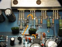
The attached photo shows the drivers from a working amplifier. The U07/57 is hidden but you can use the code at the top of the transistor to see which is the 07 and which is the 57.
Check the drivers before reusing them.
If you have MPSA06s and MPSA56s, you may want to use them to get the amp playing and then install the larger drivers after you've found all of the problems.
In the orange channel, you can see that the low side transistors are being biased on (barely but enough to allow them to conduct). This would cause a negative DC output. The high side outputs are probably on also (although 0.4v isn't generally enough to make BJTs conduct). If both are on, the amp would certainly draw excessive current.
The attached photo shows the drivers from a working amplifier. The U07/57 is hidden but you can use the code at the top of the transistor to see which is the 07 and which is the 57.
Check the drivers before reusing them.
If you have MPSA06s and MPSA56s, you may want to use them to get the amp playing and then install the larger drivers after you've found all of the problems.
Attachments
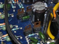
well...it looks like someone who worked on it before me put those circled drivers in backwards.
i'll get back when i get some AO6/56.
this amp is driving me nuts...
i'll get back when i get some AO6/56.
this amp is driving me nuts...
If you look at the pads for the drivers, you'll see one is square. That is almost always pin 1.
The only exception that I know of is for the jfets (in the muting circuit) in Orion amplifiers.
The only exception that I know of is for the jfets (in the muting circuit) in Orion amplifiers.
yeah i was supicious of it from the beginning, but i heard it play with the drivers backwards so didnt give it much consideration.
i guess now i know why it blew....oh btw after rearranging them, that high current (100 amp )draw stopped, now its only around 12 amps.
a couple sets of those 2ne's get hotter than the others....i hope the AO6/56 hold up for testing..since the 2ne's themselves are heating up.
that lone 2NE5639 was also backwards.
That's a Jfet. They're installed with pin 3 in the square pad.
If the TO-220 case transistors are getting hot, the smaller transistors don't have much of a chance.
Have you rechecked all of the output transistors?
If the TO-220 case transistors are getting hot, the smaller transistors don't have much of a chance.
Have you rechecked all of the output transistors?
asking someone to check all the outputs on an old school orion amp...is like asking them to pull a tooth, all 20 of them... 
i know i can just take off the base and emitter legs..but, but, but
but i have to do it...
i remember the jfet situation from a previous 225 hcca you helped me fix, with a defective muting cicuit.
time to start pulling...
i know i can just take off the base and emitter legs..but, but, but
but i have to do it...
i remember the jfet situation from a previous 225 hcca you helped me fix, with a defective muting cicuit.
time to start pulling...
Use a hot iron and add extra solder to the pads. Lay the iron across all 3 legs and wipe the transistors off of the board. It takes about 3-4 seconds each with a good iron.
All you have to check are the ones in the channel where the drivers were installed backwards.
If you use the limiting resistor and measure the voltage across each of the emitter resistors, it may lead you to the problem (without removing the transistors).
All you have to check are the ones in the channel where the drivers were installed backwards.
If you use the limiting resistor and measure the voltage across each of the emitter resistors, it may lead you to the problem (without removing the transistors).
well checked the transistors, all were good
pulled the 2ne's im using as drivers (taken out of board) and the vdc on the speaker outputs went away.
the 2ne's were still good.
checked all the resistors and diodes on the orange side, all were good.
must be something inline before the 2ne's and a56/06 pre-drivers
is there any chance the opamps could be suspect?
i know im getting close, but when it comes to signal paths i just get lost.
There are 4 diodes in series. They are pulled toward the rails by two 18.2k ohm resistors. If you measure across the 4 diodes (where they connect to the resistors), you should read ~2v DC. If it's more than ~3v, that could be a problem. The predrivers should be removed for this. The outputs and the drivers can remain.
If you install only the outputs (no drivers or predrivers), do you have any DC offset or current draw?
Leaving the outputs in... If you install the drivers (the transistors that connect to the base of the outputs through ~2.7 ohm resistors), do you have any DC or excessive current draw?
Are you sure the outputs are in the correct locations?
The op-amp could cause DC offset but not excessive current draw. Excessive current draw is generally due to having opposing transistors 'on' at the same time.
Perry Babin said:There are 4 diodes in series. They are pulled toward the rails by two 18.2k ohm resistors. If you measure across the 4 diodes (where they connect to the resistors), you should read ~2v DC. If it's more than ~3v, that could be a problem. The predrivers should be removed for this. The outputs and the drivers can remain.
------------------- getting 1.92vdc
If you install only the outputs (no drivers or predrivers), do you have any DC offset or current draw?
------------------- drawing 1 amp....orange channel has
-0.049vdc red l ead on orange wire/black lead on orange black stripe........yellow channel 0.0vdc
Leaving the outputs in... If you install the drivers (the transistors that connect to the base of the outputs through ~2.7 ohm resistors), do you have any DC or excessive current draw?
----------------- current draw is relatively the same....but get -10.64vdc on orange channel...yellow gets 0.045vdc
Are you sure the outputs are in the correct locations?
-----------------
The op-amp could cause DC offset but not excessive current draw. Excessive current draw is generally due to having opposing transistors 'on' at the same time.
---------------- the excessive current problem is gone, ever since i flipped those two backwards drivers
if the guy before me put the transistors in wrong, im going to track him down and............. 😎
An externally hosted image should be here but it was not working when we last tested it.
as of right now the A56/O6 are still out of the board
If the yellow channel isn't causing problems, you can leave all of the parts in it.
The drivers and predrivers are (were) the U07s and U57s.
You can identify the drivers by measuring the resistance between their collectors and the collectors of the outputs. All are directly connected.
The base of the predrivers is directly connected to the point where the 4 series diodes connect to the resistors. One predriver connects to one end of the diodes and the other predriver connects to the other end of the diodes.
Using the information above, are you sure you installed only the drivers and no predrivers?
ohhh, ok now i get it, the 057/07 drive another set of 057/07
i thought the a56/06 in my picture in the previous page were the pre drivers...
what are those a56/06 for? because i took them out. please look at previous page pic.
i thought the a56/06 in my picture in the previous page were the pre drivers...
what are those a56/06 for? because i took them out. please look at previous page pic.
pulled the pre drivers for orange channel and got the same number...i think i measured the wrong legs previously and got 1.92....but still the same if i measure the same legs
for the two legs (correct legs)top and bottom by the tantulums, this time im getting 2.5
no excess current draw...no dc on speaker outputs
readings for the yellow channel are the same...
for the two legs (correct legs)top and bottom by the tantulums, this time im getting 2.5
no excess current draw...no dc on speaker outputs
readings for the yellow channel are the same...
may have found the problem, the ne5534 isnt getting vcc+ only vcc-
now i just have to figure out why... 🙁
now i just have to figure out why... 🙁
The NE5534 has the positive regulated input on pin 7, not pin 8.
Measure the voltage across the two center legs of the predrivers. Is that 2.5v?
For the orange channel only, with no power applied to the amp, what is the resistance from the first leg of the predrivers to the RCA shield ground (two resistance values)?
What's the resistance from the third leg of the predrivers to the positive and negative rails (4 resistance values). The emitter resistors go to the rails so you can use them as the rail connection.
If you'd like, you can compare the readings above to those in the other channel but they should be the same.
The NE5534 has the positive regulated input on pin 7, not pin 8.
----- yep, downloaded the data sheet for a philips device, voltage is 0.000 vdc
Measure the voltage across the two center legs of the predrivers. Is that 2.5v?
----- yes sir, getting 2.5 vdc (put A56/06 in because i pulled a via)
For the orange channel only, with no power applied to the amp, what is the resistance from the first leg of the predrivers to the RCA shield ground (two resistance values)?
-----140.5 & 140.8 ohms
What's the resistance from the third leg of the predrivers to the positive and negative rails (4 resistance values). The emitter resistors go to the rails so you can use them as the rail connection.
A56
================
red on third leg
negative rail= 29.4m ohm
positive rail = -1.61m ohm noise in PS
================
black on third leg
negative rail= -4.3m ohm
positive rail= OL no reading and same noise
-------------------------------------------------------------------
-A06
================
red on third leg
negative rail= OL and same noise in PS
positive rail = -1.4 to -4.4m ohm (this guy changes everytime i measure it)
=================
black on third leg
negative rail= -1.61m ohm and same noise in PS
positive rail= 206 ohm
=================
sorry , didnt know where i should put each lead.
im starting to get the feeling this amp is pretty screwed up...in more ways than one...
The amp may have a few problems but it's not badly damaged. We just have to narrow the problem down and it takes a bit of time.
If the amp was off when you measured the resistance between the rail and the third leg of the predrivers, you have 2 open/defective resistors. You should read 75-100 ohms between the collector (third leg) of the predrivers and one of the rails.
This is how they're connected:
NPN predriver collector >> 75-100 ohm resistor >> emitter resistor of 6491
PNP predriver collector >> 75-100 ohm resistor >> emitter resistor of 6488
Check the resistors and continuity between the resistors and transistors.
Also check for continuity between the collector of the predrivers and the base of the drivers.
The reg should be easy to troubleshoot. Confirm that you have rail input on pin 3 and output on pin 2 of the LM317. See the attached photo for the circuit path to the 5534. Both 5534s are powered by the same reg.
Attachments
those pre drivers were measured with the power on. 
here they are again with power off: 😉
----------------------------------------
A56
----------------------------------------
red on third leg
negative rail= 100 ohm
positive rail = -1.61m ohm
================
black on third leg
negative rail= 100 ohm
positive rail= 2.38 ohm
----------------------------------------
A06
---------------------------------------
red on third leg
negative rail= 2.4m ohm
positive rail = 100 ohm
=================
black on third leg
negative rail= -1.5m ohm
positive rail= 100 ohm
=================
are they good?
which lead goes where? this is kinda confusing...
------------------------------------------------------------------------
This is how they're connected:
NPN predriver collector >> 75-100 ohm resistor >> emitter resistor of 6491
PNP predriver collector >> 75-100 ohm resistor >> emitter resistor of 6488
Check the resistors and continuity between the resistors and transistors.
>>>>>>>> you lost me here, i thought the pre drivers go to
the drivers first? im trying to follow the collector of
the pre driver, but the first thing the a56 hits is the
base of the driver.....the other pre driver hits a
mylar cap, then hits the base of the other driver.
i'd really appreciate a pic of this one, its throwin
me off bad...
------------------------------------------------------------------------
Also check for continuity between the collector of the predrivers and the base of the drivers.
>>>>>>>> 0.2 ohm for both
------------------------------------------------------------------------
The reg should be easy to troubleshoot. Confirm that you have rail input on pin 3 and output on pin 2 of the LM317. See the attached photo for the circuit path to the 5534. Both 5534s are powered by the same reg.
>>>>>>>> pin 3= 25 vdc
pin 2= 14 vdc
black lead on rca shield ground
-------------------------------------------------------------------------
question regarding the missing 2ne5369 muting transistors, do the holes need to be filled in to take proper measurements?
In general, you never use you meter on diode check or ohms when voltage is present in the circuit. The voltage in the circuit will skew the results.
The resistors look OK.
The reg looks OK. The resistor between the diode and the IC is likely open.
The muting transistors don't need to be in the circuit.
Did you see this? It was posted earlier.
http://www.bmpt1.com/images/orion01.swf
The next step is to reinstall the predrivers. Be sure to get them in the correct locations (NPN and PNP in the correct locations).
Before you power it up, solder a small jumper wire across two of the biasing diodes (the 4 diodes in series). Solder a jumper across each of the two center diodes. I want to be sure that the predrivers are not biased on.
If the predrivers are out of the other channel, leave them out.
Power up the amp. Does it draw excessive current?
like this? i just want to make sure, so i can stop being redundant.
ABCDE?
ABCDE?
An externally hosted image should be here but it was not working when we last tested it.
- Status
- Not open for further replies.
- Home
- General Interest
- Car Audio
- 2150sx component location