"shunt Schade" is new to me can you send me a schematic please?
I have a lot of nos PL509, their curves doesn't look linear at all, it is possible to make these linear?
I have a lot of nos PL509, their curves doesn't look linear at all, it is possible to make these linear?

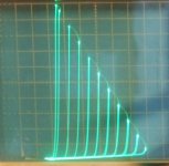
This is the 1650T square wave response. The secondary is loaded with 8R the primary is connected to a signal generator with 2k2 in series as a rough approximation to the plate load.
yellow - source
blue - voltage primary
green - voltage secondary
red - current in 2k2
I'll stop now as it messing up the thread.
"shunt Schade" is new to me can you send me a schematic please?
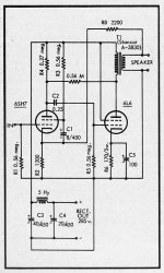
The 0.56 Meg resistor from the 6L6 plate to the 6HS7 plate, in the diagram below, is the "shunt Schade" N Fdbk.
(There is global N Fdbk in there too, to the 6SH7 cathode.)
O.H. Schade wrote about a similar series N Fdbk scheme in 1938, using an xfmr. to put some plate signal in series with the input grid.
The shunt case here, using just a resistor plate to plate, has become the more common approach. It requires a current source (pentode) to drive the resulting low input impedance to the next tube. That's the penalty. It linearizes the output tube and lowers it's output impedance, the benefits. Calling it "shunt Schade" is somewhat of a slang shortcut to identify just this specific case of shunt N Fdbk. The N Fdbk combined with the driver gm sets a forward gain, or "Mu", and the resulting plate curves look very much like a high quality triode. Much better typically than the internal triode (using g2 tied to plate ) offers.
Local feedback between grid-cathode
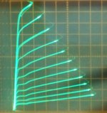
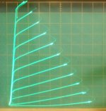
There is also another scheme that linearizes pentodes and leaves them as pentodes. Called 'Crazy/Twin" drive. Second and 3rd pic below show before (grid 1 drive) and after curves (Crazy/Twin) for a 26LX6 Sweep tube. A whole new ball game there. A moderate learning curve there, several threads on it.
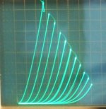
The last two pics show a 6HB6 pentode in internal triode mode, and then in shunt Schade mode. The N Fdbk was set -very- strong in this last case, so the curves are not as obviously triode like, but this shows how the "rollover" in the internal triode curves is fixed into equal spacing with very low Rp. Using a higher "Schade" resistor (less N Fdbk) will give nice typical triode like curves (like a typical DHT or 211).
Attachments
Last edited:

Thanks for sharing,
How is lundahl 1691B in midrange?
Mid FR is reasonably flat.
The purple curves above in post 15 (3rd pic) show "shunt Schade" modeled on a KT88, adjusted to look similar to a 300B.
The Hammonds sound and measure pretty darn good for the money. I tried 5k, 6k and 10k on my last boat anchor, later replacing with monolith magnetics at 4x the cost
It was an improvement but to be honest, the bass was a little better with the Hammond
It was an improvement but to be honest, the bass was a little better with the Hammond
The Hammonds sound and measure pretty darn good for the money. I tried 5k, 6k and 10k on my last boat anchor, later replacing with monolith magnetics at 4x the cost
It was an improvement but to be honest, the bass was a little better with the Hammond
did the cost justify the improvements?
Thanks for sharing smoking-amp, i will have in mind.
But I have some nos 211 and want to build this amp, the only problem is the output transformer.
I read an other thread that 211 needs 16K load.
Does anyone knows any old amplifier using 211?
I want to compare how they use this tube.
In the RCA datasheet recommend at 1250v Rload=9600
But I have some nos 211 and want to build this amp, the only problem is the output transformer.
I read an other thread that 211 needs 16K load.
Does anyone knows any old amplifier using 211?
I want to compare how they use this tube.
In the RCA datasheet recommend at 1250v Rload=9600
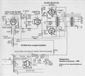
Jeez, at 16K it's time for some drastic measures.
Either use two 211 in parallel, or use two 8K OTs in a N. Crowhurst Twin Coupled design to get 16K. The driver stage design will be from Hell though, a KV drive signal! Could use a beam tetrode, like a TV Sweep, for the driver with bootstrapping for the plate load resistor. That would effectively remove most of the CFB effect at the output stage. 6GF5, 6GE5...
Yeah, that's actually not a bad solution I think. Two cheap OT's and a bootstrapped Sweep tube driver. The OT Watt ratings add up. They each handle only half the AC voltage swings. Make sure to get 16 Ohm secondaries to end up with 8 Ohms when paralleled. One concern to check would be the DC rating of the plate side OT, for safety too.
Attachments
Last edited:
did the cost justify the improvements?
I think the question is a bit subjective and i’m leaning more to a yes since they did cost an “arm and a leg” 🙂
They did measure better
But I have some nos 211 and want to build this amp, the only problem is the output transformer. I read an other thread that 211 needs a 16k load
In the RCA datasheet recommend at 1250v Rload=9600
I don’t see why you would need 16k, do you use Ltspice? Calculate some different scenarios, only thing that will change is distortion. It should be low enough where it probably wont make much of a difference.
The higher the voltage, the higher Rload, the datasheet is just a recommendation. Personally, i would run it at 1150-1200v
Last edited:
None want to share with me his experience?
So far I have found
Hammond 1638SEA 10K, 30W, 90mA, 88H
about 400 euro for the pair
Sowter SA11 10K, 25W/20Hz, 70mA, 80H
about 850 euro for the pair
ISO FC-40-10S 10K, 40W/30Hz, 70mA, 80H
1750 euro for a pair
I am very happy with the ISO
I am very happy with the ISO
Thanks for sharing, can you be more detail about the sound, (bass-midrange-highrange), do you have any measurements?
The price is very high for me, but it is interesting to know
I don’t see why you would need 16k, do you use Ltspice? Calculate some different scenarios, only thing that will change is distortion. It should be low enough where it probably wont make much of a difference.
The higher the voltage, the higher Rload, the datasheet is just a recommendation. Personally, i would run it at 1150-1200v
I haven't used Ltspice before, may i will give a try. I want to get maximum power at A1 class, so i was thinking Va=1250V with cathode bias at 60mA.
I think is opposite, the higher the voltage the lower the resistance
Last edited:
Thanks for sharing, can you be more detail about the sound, (bass-midrange-highrange), do you have any measurements?
The price is very high for me, but it is interesting to know
About measurements, 20-20000 0 dB.
Sound is sweet but dynamic, lot of details, nice colours , large stage, and really goes low with 211.
I think I got what I paid for.
But I think also perhaps there are other very good 10k OPT.
Gilles.
OH, right, I forgot this has to be for SE.
Surprisingly, the N. Crowhurst Twin Coupled design still works for that too.
Just use two 8k SE OTs, one in the cathode circuit and one in the plate circuit to get a 16K resultant. Bootstrapping for the driver stage load R can still come from the cathode circuit. The Watt ratings of the two OTs add up still. So Hammond 30 Watt SE OTs say, would add up to a 60 Watt SE.
The cheaper Edcor 8K SE only has a 6 Ohm secondary, so won't work here for Twin Coupled.
Gee, Hammond has a 75 Watt 5K SE model too, how about 40x 6197s in parallel for 150 Watts SE output. ($0.33 each) 🙂
Well, 7x 6197s in parallel to do 25 Watt SE. (the GE JAN 6197 are very consistent tubes, almost randomly matched.)
A quite practical solution to very Hi Z primary needs. The OTs will still need a 16 Ohm secondary for paralleling into an 8 Ohm output. (the Hammond SEs have 4,8,16 ohm secondaries) Sufficient DC rating important for the plate side OT still.
Last edited:
OH, right, I forgot this has to be for SE.
Surprisingly, the N. Crowhurst Twin Coupled design still works for that too.
Just use two 8k SE OTs, one in the cathode circuit and one in the plate circuit to get a 16K resultant. Bootstrapping for the driver stage load R can still come from the cathode circuit. The Watt ratings of the two OTs add up still. So Hammond 30 Watt SE OTs say, would add up to a 60 Watt SE.
The cheaper Edcor 8K SE only has a 6 Ohm secondary, so won't work here for Twin Coupled.
Gee, Hammond has a 75 Watt 5K SE model too, how about 40x 6197s in parallel for 150 Watts SE output. ($0.33 each) 🙂
Well, 7x 6197s in parallel to do 25 Watt SE. (the GE JAN 6197 are very consistent tubes, almost randomly matched.)
A quite practical solution to very Hi Z primary needs. The OTs will still need a 16 Ohm secondary for paralleling into an 8 Ohm output. (the Hammond SEs have 4,8,16 ohm secondaries) Sufficient DC rating important for the plate side OT still.
I am not excited with the Idea of two outputs, i prefer parallel se
I have in plans to build an PSE el84 with 4 tubes per channel in triode mode about 8 watts with 1250 ohms load impedance.
What load need for 7x6197 ? 25watt in triode mode?
Were do you buy so cheap?
Last edited:
I am not excited with the Idea of two outputs, i prefer parallel se
Hammond makes an affordable transformer for three type 211 in parallel, with 5K Ohm primary. Can also be used with a single Eimac 304TL interchangably. Same filament requirements, same mu (12), different socket(s).
All good fortune,
Chris
What load need for 7x6197 ? 25watt in triode mode?
Were do you buy so cheap?
6197 with gm of 11000 and internal Mu of 22 would give an Rp of 2000 Ohm at 30 mA idle. 7.5 Watt Pdiss.
The 7x 6197 was just a napkin scribble guess for how many tubes to get 25 Watts out in pentode mode, class AB.
For 25 Watts in triode mode, and class A, that would take more like 16x 6197 tubes. 16 tubes in parallel would give 125 Ohms Rp equivalent for the bunch. Figuring 5X that for triode operation with low distortion would require a 625 Ohm primary SE OT. A rough estimate anyway for continuous operation. (class A)
So, I guess 300 Watts in class A would take around 192 tubes. $63 of tubes. $400 of sockets. Whew! At least you won't need an OT with 19.2 peak Amps available. Forget that idea.
Well, I guess that could be scaled down considerably if taking audio crest factor into account in class AB. Maybe 50 tubes would work for peak power intermittently in class AB. Just not for continuous sinewave.
The $0.33 price comes from a tube sale at Bangy-Bang tubes (on Ebay) early this year of military surplus stock in high quantity. 200 tubes per box. Normally that place is hideously expensive for single tubes, so I guess they do some volume sales occasionally (of overstock) to keep people checking their website or Ebay store. When an Ebay sale says "serious tubes" I figure a SERIOUS $$$ price goes with it.
I have seen some prices on 6197 tubes on Ebay recently in the $0.50 (60 quantity) up to $2 range lately.
Last edited:
Tamura's F-2013A may be the one choice. One of the best transformer maker in Japan.
https://www.tamura-ss.co.jp/file.jsp?id=18665
Unfortunately I never used one because I can't afford.
https://www.tamura-ss.co.jp/file.jsp?id=18665
Unfortunately I never used one because I can't afford.
- Home
- Amplifiers
- Tubes / Valves
- 211 output transformer suggestion