")
Why are you quoting me?
I have nothing to do with Edcor, but I do use some of their P-P OTs.
Their SE 10K OT quotes 200 mA DC which is probably a typo. No info on inductance that I see. Cheaper than the ones mentioned so far, but shipping overseas will be high. I would get some real data from Edcor before considering the 10K OT.
10K or above is a tough OT to make well.
Last edited:
Type 211 (mu = 12) is a difficult valve to match to. Nice loadlines are in the 15K Ohm range. It's so difficult that I might consider a combination of choke and capacitor coupled step down transformer, which can be made smaller for less parasitics.
Or, run three in parallel. Yikes.
All good fortune,
Chris
Or, run three in parallel. Yikes.
All good fortune,
Chris
I assumed you were the guy from TUBELAB.Why are you quoting me?
I have nothing to do with Edcor, but I do use some of their P-P OTs.
This guy?
tubelab is George, smoking-amp is Donald if i am not mistaken....
you betcha, so i avoid these hv tubes......6c33c with its low ri is more of a joy to make...
10K or above is a tough OT to make well.
you betcha, so i avoid these hv tubes......6c33c with its low ri is more of a joy to make...
AE Europe and Monolith magnetis are respectable European OPT winders you should also check:
Audio transformers
product & prices | MONOLITH MAGNETICS
Audio transformers
product & prices | MONOLITH MAGNETICS
Thanks everyone for reply
Edcor CXSE25-10K are missing data..
15K is better, but more difficult and not so popular, needs a super specialist in audio transformers for low leakage and low capacitance and will be very costly!
PSE 211 needs an output at 40W class A1, and also double power to all(power supply)
I select 211 not only for the power but for the sound quality, 6C33C sound as good as 211?
I have hear good words for AE europe but doesn't have a standard range catalogue, so we don't know the price and usually needs two months after the order.
I like very much the specifications in output transformers from Monolith magnetics but not for 211. 8K4 impedance only?
I select 211 not only for the power but for the sound quality, 6C33C sound as good as 211?
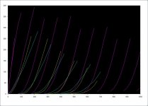
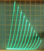
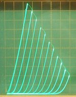
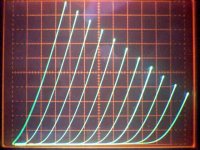
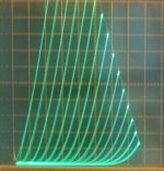
211 has near perfect Triode curves (pic 1 below), 6C33 doesn't compare (pic 2 below).
There ARE some ways to get near perfect Triode curves for less $$$ and a more practical OT (lower primary impedance). One way is to use "shunt Schade" on a beam tetrode like the KT88 (pic 3 below and link below) or on one of the TV "Sweep' tubes. This approach gets you a low Rp as well. Not much to complain about here.
Another is to use a TV "Sweep" that has good Triode curves to begin with. Curve tracer selection recommended here. (pic 4) These unfortunately tend to suffer "runaway" over time. They don't like HV on the grid 2. You could put a cap bypassed CCS under the cathode to protect against runaway damage and use lowish B+, but you may still need to change the tube. (ie, regularly)
George (Tubelab) has been working on a reduced screen V Triode scheme for pentodes. Usually these use a Mosfet follower for the screen, driven by an R divider between plate and cathode. This makes the Mu factor and Rp go up however, but keeps the screen V down for reliability. It also mimicks the internal g2/g1 triode curves, so you need to start with a tube which already has good triode curves. One could combine this approach with some light "shunt Schade" to clean up the triode curves some, lower the Rp and more equal curve spacing.
Then there is the option of paralleling a bunch of super triode curve small tubes (pic 5 below), curve tracer matched.
And then there is the scheme of using a suitable small triode model (pic 6 below) with an "emulation" Fdbk driver to control a large high current tube (typically a Sweep) to copy it's characteristics. The STC super triode scheme is one version of this. (see thread)
https://www.diyaudio.com/forums/tubes-valves/340415-local-feedback-grid-cathode-3.html#post5858884
Attachments

Last edited:
Most later development tubes were more optimized for gm than linearity. Their triode mode curves tend to look like the 6C33 curves above. The grid 1 is pushed closer to the cathode to get more gm, but suffers from "island effect" or "inselbildung". (grid wire proximity effects)
There are some exceptions, like some of the green curves above, but not too many. You need a curve tracer to select them besides.
One small tube (7.5 Watt Pdiss) I have found recently (6197/6CL6) has fairly good triode curves (not quite super triode curves, but close), and is amazingly consistent from tube to tube, and they were $0.33 each in quantity. (see triode mode curves below) Suitable for paralleling. For $2 you get a 45 Watt 300B with 66000 gm and Rp of 333 ohms. Not much to complain about here either.
Attachments
Last edited:
How on earth are you supposed to get "group delay" in a transformer.?good frequency response and low group delay primary to secondary.
It's has no Hysteresis whatsoever, what instant voltage change in = magnetic flux goes in = magnetic flux out = instant voltage change out.
What nonsense is this now?
Are yes as you get to HF between primary and secondary the gain will drop and the phase will deviate from 0 degrees and start to lag. As you know group delay is just rate of change of phase with frequency. It turns out that the leakage inductance in combination with the distributed capacitance does seem to model to produce a fairly constant group delay for a transformer. So for the hammond 1650T if you measure the delay between a 1KHz sinewave in on primary and secondary out its about 2us. Its much the same for 10KHz. If you prefer to keep to phase and gain thats just fine too.
Last edited:
- Status
- This old topic is closed. If you want to reopen this topic, contact a moderator using the "Report Post" button.
- Home
- Amplifiers
- Tubes / Valves
- 211 output transformer suggestion