Hi GM, thanks for the tips about the decorative weight, definitely seems like an effective/attractive solution.
PS I've used the term relatively lightweight since I've chose Light MDF which is about 15~20% lither than standard MDF, but apparently that's not the case, since the material used on those sheets are radiata pine fiber(a very soft wood) according to the manufacturer, now I decided to make the front baffle of triple 5/8" sandwich to hold the 21SW152 and stay in the safe line, so I expect the box will be about ~140Lbs without the driver.
Most likely the next project will be a hand-truck to move this coffins.
Regards
You're welcome! Yeah pretty heavy for me nowadays, so have a decent large appliance hand truck; but by 'lightweight' I meant thin no void plywood with scrap pieces or similar for panel bracing and all [6] panels + driver tied together with threaded rod to keep it from 'breathing' as well as for added weight support.
Thanks GM for the clarification on the lightweight technique you've mentioned, that seems like another solution if carefully executed indeed.🙂
Between I've found the old Sketchup Make 2013, the early version when Trimble took over, this old version run flawless under an Windows 7 VM since I'm on Linux, unfortunately latest Sketchup don't work in VirtualBox since it need HW video acceleration, also they don't work in WINE either.😉
The models I've made are a very simple/basic representation of the sub as it was my first time using that sketch software, so I still need to learn alot. about it.


Changes since the initial idea:
*Side walls top & bottom will be 1.25" tick, 2x 5/8" sandwich.
*Front baffle will be 1.88" thick, 2x 5/8" sandwich plus a later added 5/8" panel for speaker flush.
*Black matte laminate to match my diy main speakers
* Top & Bottom will have rib style bracing, and the center too.
*Final enclosure measures are 42"H x 24"W x 27.15"
Observations that should be considered:
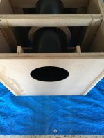
Initially I wanted the port to be 36" long, however since the enclosure will measure 39.5" internally from top to bottom, then subtracting 1.25" from the 36" port equals 34.75"(port will be inserted on the bottom), so 39.5" minus 34.75" will bring a port clearance of just 4.75" from the top, this seems too close for an 8" dia port and may ran into audible noise/compression.
So my solution so far is to sacrifice 2" from the port and make it 34", this will bring a port clearance of 6.75" from the top with just a tad higher port tune, still non ideal but I hope experienced users ports position/clearance may chime in, since I've read that the rule of thumb is to give a port clearance as big as the port diameter.
Really hope I can go with the 6.75" port clearance(closer by just 1.25") with no major noise/compression issues, as this boxes will not be pushed to the max between.😕
P.S. The port has a 3" space from the back wall, this is to have clearance to spare from the speaker neodymium magnet.
For reference here's the WinISD model with the port cut to 33", in comparison with my current UM18-22 sealed:

Expected usable frequency response after EQed:

Regards
Between I've found the old Sketchup Make 2013, the early version when Trimble took over, this old version run flawless under an Windows 7 VM since I'm on Linux, unfortunately latest Sketchup don't work in VirtualBox since it need HW video acceleration, also they don't work in WINE either.😉
The models I've made are a very simple/basic representation of the sub as it was my first time using that sketch software, so I still need to learn alot. about it.
Changes since the initial idea:
*Side walls top & bottom will be 1.25" tick, 2x 5/8" sandwich.
*Front baffle will be 1.88" thick, 2x 5/8" sandwich plus a later added 5/8" panel for speaker flush.
*Black matte laminate to match my diy main speakers
* Top & Bottom will have rib style bracing, and the center too.
*Final enclosure measures are 42"H x 24"W x 27.15"
Observations that should be considered:
Initially I wanted the port to be 36" long, however since the enclosure will measure 39.5" internally from top to bottom, then subtracting 1.25" from the 36" port equals 34.75"(port will be inserted on the bottom), so 39.5" minus 34.75" will bring a port clearance of just 4.75" from the top, this seems too close for an 8" dia port and may ran into audible noise/compression.
So my solution so far is to sacrifice 2" from the port and make it 34", this will bring a port clearance of 6.75" from the top with just a tad higher port tune, still non ideal but I hope experienced users ports position/clearance may chime in, since I've read that the rule of thumb is to give a port clearance as big as the port diameter.
Really hope I can go with the 6.75" port clearance(closer by just 1.25") with no major noise/compression issues, as this boxes will not be pushed to the max between.😕
P.S. The port has a 3" space from the back wall, this is to have clearance to spare from the speaker neodymium magnet.
For reference here's the WinISD model with the port cut to 33", in comparison with my current UM18-22 sealed:
Expected usable frequency response after EQed:
Regards
Last edited:
You could reduce the port clearance to just 2" from the top without reducing the area of the port inlet, audible noise/compression would be no problem.View attachment 954094View attachment 954093View attachment 954095
... a port clearance of just 4.75" from the top, this seems too close for an 8" dia port and may ran into audible noise/compression.
So my solution so far is to sacrifice 2" from the port and make it 34", this will bring a port clearance of 6.75" from the top with just a tad higher port tune, still non ideal but I hope experienced users ports position/clearance may chime in, since I've read that the rule of thumb is to give a port clearance as big as the port diameter.
The reason for the "rule of thumb" is a port clearance less that a port diameter will effectively begin to lengthen the port, lowering Fb while also virtually reducing cabinet volume.
The port within 3" from the back wall and the brace structure ring you depict surrounding the duct do the same.
As Josh Ricci wrote about his 21SW152-4 build: "The target tuning was 28Hz, but the proximity of the vent opening to the back wall of the cabinet lowered the effective tuning to about 25Hz instead. "
Data-Bass: Subwoofer Measurements
I'd suggest testing the Fb before gluing the speaker baffle or port brace structure ring in place so you can adjust length to the frequency you want.
Art
Last edited:
Hi weltersys, thanks for the clarifications on the port clearance rule of thumb and its effects wen in close proximity to walls, learned new thing though I still need a long road to learn.🙂
Great info on the Data-Bass indeed, I've been reading on subs performance on Data-Bass for a while, in fact his extreme testing on the B&C's made me choice this subs for my 2-CH music setup.
Looks like the DATS V3 is still in back-order on PE, however since you've denoted that the effect in wall close proximity and the port reinforcement ring may lower the Fb rather than making noise/compression, guess it will be fine as the initial wanted tuning was around ~17 but had to raise it a tad due the wanted box size, so that's a relief since this is for 99% music playback.
P.S. I've read the lower the Fb is preferred to keep the group delay at minimal possible but guess is not a big deal on subs, OTOH that port wall proximity effect effectively lowering cab internal volume is another compromise.
Regards
...guess it will be fine as the initial wanted tuning was around ~17 but had to raise it a tad due the wanted box size, so that's a relief since this is for 99% music playback.
OTOH that port wall proximity effect effectively lowering cab internal volume is another compromise.
Regards
Since you listen mainly to rock, oldies and electronic music, choosing an Fb near an octave below the fundamental frequencies used in most of that music is another compromise to consider when it comes to SPL output in the 30-60 Hz range.
Can't have everything, so we all get to choose our own compromises 😀
Art
Small update!
Been few months since my last entry in this project, just wanted to update that my plan are to finish this project by October hopefully.
So far I've glued the boxes back and the side panels totaling 6 x 24"W x 42"H sandwiches, as usual I just used TB3 for the glue layers and a lot of old weights and old concrete blocks for set them for 24 hours.😱
Next move is the top and bottom sandwiches and the port assembly, the last part is the now triple-baffle to flush mount the subwoofers.


Early build progress can be found in the project Google Photos
Been few months since my last entry in this project, just wanted to update that my plan are to finish this project by October hopefully.
So far I've glued the boxes back and the side panels totaling 6 x 24"W x 42"H sandwiches, as usual I just used TB3 for the glue layers and a lot of old weights and old concrete blocks for set them for 24 hours.😱
Next move is the top and bottom sandwiches and the port assembly, the last part is the now triple-baffle to flush mount the subwoofers.
Early build progress can be found in the project Google Photos
Update:
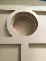
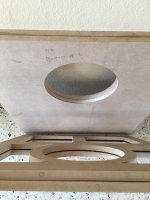
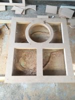
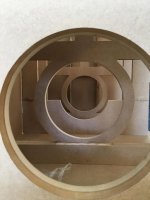
I just started to cut the 20" baffle circles with a homemade Router Jig made of some scrap 1/4" plexiglass(acrylic) I had lying around, it worked just fine so far.🙂
I will cut one hole to make a double 5/8 sandwich first then route the other side after glue sets, then cut the bigger hole to flush mount the drivers and glue them after woofer dry-run fit test.😉
More to come, here are some shots of the dusty work:
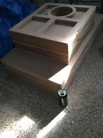
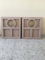
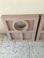
Here is another update on this 21" subwoofers "build".
Since this thread was initially for design "suggestion" between straight slot-port vs round-port(opted for the round-port), I will start a new build thread on this subs design after the internal enclosure assembly is ready.
Today I just did a driver dry-run test on the baffles to test the flush panel measures and to mark the bolt circle to install the T-Nuts, tomorrow after release the T-Nuts holding screws I will glue the third 5/8" flush panel then start with with the rest.😎


All images in the Build Google Photo Album
Since this thread was initially for design "suggestion" between straight slot-port vs round-port(opted for the round-port), I will start a new build thread on this subs design after the internal enclosure assembly is ready.
Today I just did a driver dry-run test on the baffles to test the flush panel measures and to mark the bolt circle to install the T-Nuts, tomorrow after release the T-Nuts holding screws I will glue the third 5/8" flush panel then start with with the rest.😎
All images in the Build Google Photo Album
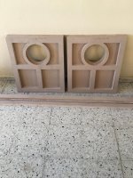
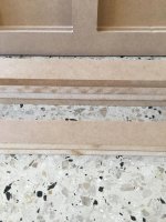
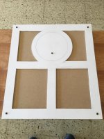
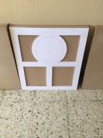
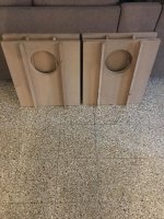
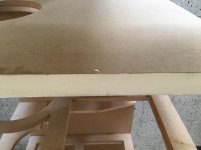
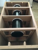
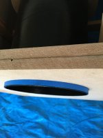
Just finished the triple baffles sandwiches and also cut the 12x top/bottom panels, 4 of them will works as brace + port support.


Here I've used some formica leftovers to make a tape as a cutting guide, I had to sand the edges to smooth the cuts regardless.😱


Here are 2 cuts already flattened out(the port bottoms).


Here sanding the port edges and applying a little spread of wood glue to reinforce the cardboard port edges grain, still deciding whether to paint them inside/outside, or just the port inside.


More to come: Photo Build Log
Here I've used some formica leftovers to make a tape as a cutting guide, I had to sand the edges to smooth the cuts regardless.😱
Here are 2 cuts already flattened out(the port bottoms).
Here sanding the port edges and applying a little spread of wood glue to reinforce the cardboard port edges grain, still deciding whether to paint them inside/outside, or just the port inside.
More to come: Photo Build Log
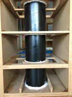
Another quick update!
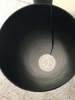
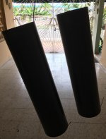
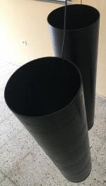
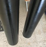
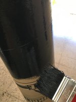
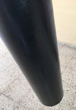
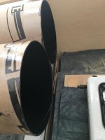
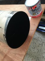
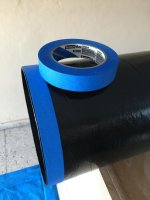
I just decided to paint the cardboard tubes both inside/outside to increase the ports longevity and to protect it from those bugs who like cardboard, I've used standard oil-alkyd black enamel and applied them a generous coats.😉
Here is the reinforced tube edges after the wood glue dried up, looks like a half rubber gasket.😎

Here are the tubes drying up, and I'm in the making of the port/brace section template made of a 1/4" PVC sheet for routing, more to come.
I just decided to paint the cardboard tubes both inside/outside to increase the ports longevity and to protect it from those bugs who like cardboard, I've used standard oil-alkyd black enamel and applied them a generous coats.😉
Here is the reinforced tube edges after the wood glue dried up, looks like a half rubber gasket.😎
Here are the tubes drying up, and I'm in the making of the port/brace section template made of a 1/4" PVC sheet for routing, more to come.
Attachments
-
 IMG_0284_Small.jpg419.2 KB · Views: 70
 -
 IMG_0288_Ed_Small.jpg426.9 KB · Views: 80
 -
 IMG_0289_Ed_Small.jpg351.2 KB · Views: 81
 -
 IMG_0290_Ed_Small.jpg521.2 KB · Views: 64
 -
 IMG_0283_Small.jpg432.1 KB · Views: 356
 -
 IMG_0276_Small.jpg405.5 KB · Views: 360
 -
 IMG_0274_Ed_Small.jpg378.9 KB · Views: 363
 -
 IMG_0268_Small.jpg421.8 KB · Views: 372
 -
 IMG_0266_Ed_Small.jpg432.8 KB · Views: 373
Update 10-25-2021
Update on the 21" Straight Down-firing Port(SDP) Subwoofers build.
Hello, I've said that this subs will be finished by late October, however the weather here is very unpredictable with tons of rain and delayed the project a bit, gladly we are safe from hurricane threats as well.
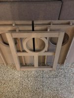
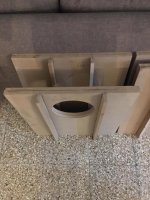
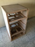
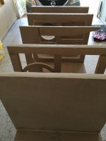
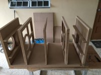
So just finished with the Ankh shaped braces and some extra cuts for the Ankh braces edges reinforcement and top/bottom ribs for added extra bracing, also I will add an additional center + back port support brace as well.
Here are some shots of the work progress, pretty much ready for dry-run assembly/test and start making a ton of centered pilot holes for gluing/assemble.
Here is the build log so far at Google Photos
Update on the 21" Straight Down-firing Port(SDP) Subwoofers build.
Hello, I've said that this subs will be finished by late October, however the weather here is very unpredictable with tons of rain and delayed the project a bit, gladly we are safe from hurricane threats as well.
So just finished with the Ankh shaped braces and some extra cuts for the Ankh braces edges reinforcement and top/bottom ribs for added extra bracing, also I will add an additional center + back port support brace as well.
Here are some shots of the work progress, pretty much ready for dry-run assembly/test and start making a ton of centered pilot holes for gluing/assemble.
Here is the build log so far at Google Photos
Attachments
-
 IMG_0360_Small.jpg590.3 KB · Views: 84
 -
 IMG_0361_Small.jpg607.6 KB · Views: 67
 -
 IMG_0363_Small.jpg498.4 KB · Views: 75
 -
 IMG_0365_Small.jpg544.6 KB · Views: 70
 -
 IMG_0359_Small.jpg535.8 KB · Views: 66
 -
 IMG_0357_Small.jpg585.8 KB · Views: 73
 -
 IMG_0351_Small.jpg486.2 KB · Views: 76
 -
 IMG_0349_Small.jpg759.8 KB · Views: 82
 -
 IMG_0345_Small.jpg466.9 KB · Views: 86
 -
 IMG_0344_Small.jpg584.6 KB · Views: 78
Update!
Hello, this 21" subwoofers are already for being assembled and laminated, however I have a question on the final glue to be used on the edge joints.😕
I've been reading a lot of good reviews on the use of PL Premium x3/x8 instead of wood glue(TB3) and I was asking if there is any advantage for it on large sub builds based my subsumptions below.
My previous build routine is to use wood glue on the edge joints(butt joints?) by applying a decent line in the edges exposing the grain and brush it evenly, then when the edge absorbs some of the glue I apply another line to bond the two pieces, of course I have a little pot of wood glue mixed with MDF dust to apply such viscous paste where I notice some gaps to help sealing, and then again after all is done I apply some small lines of caulk on the enclosure edges for final airtight sealing.
Being that the PL Premium does expand by just applying a line in the center of the wood grain to be bonded, I think that by using PL Premium I don't have to:
1: Leave the wood glue to be soaked first on the edge grain.
2: Apply again a wood glue line on the edge joint to be glued.
3: Apply wood glue mixed with MDF dust where is necessary.
4: Finishing the sealing process with latex caulk on all enclosure edges.
If the above is true, then I'm ready to get the hands dirty on the PL as it seems to be a lot easier and faster to work with, and pray I will don't have any difficult cleaning the PL mess some people talk about.
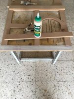
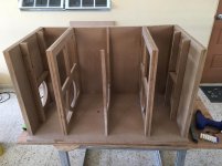
Between I leave some shots of the Top/Bottom rib style bracing to help add some stiffness, I've also reinforced the braces edges to help make the glue area to be stronger.😉
Regards
Hello, this 21" subwoofers are already for being assembled and laminated, however I have a question on the final glue to be used on the edge joints.😕
I've been reading a lot of good reviews on the use of PL Premium x3/x8 instead of wood glue(TB3) and I was asking if there is any advantage for it on large sub builds based my subsumptions below.
My previous build routine is to use wood glue on the edge joints(butt joints?) by applying a decent line in the edges exposing the grain and brush it evenly, then when the edge absorbs some of the glue I apply another line to bond the two pieces, of course I have a little pot of wood glue mixed with MDF dust to apply such viscous paste where I notice some gaps to help sealing, and then again after all is done I apply some small lines of caulk on the enclosure edges for final airtight sealing.
Being that the PL Premium does expand by just applying a line in the center of the wood grain to be bonded, I think that by using PL Premium I don't have to:
1: Leave the wood glue to be soaked first on the edge grain.
2: Apply again a wood glue line on the edge joint to be glued.
3: Apply wood glue mixed with MDF dust where is necessary.
4: Finishing the sealing process with latex caulk on all enclosure edges.
If the above is true, then I'm ready to get the hands dirty on the PL as it seems to be a lot easier and faster to work with, and pray I will don't have any difficult cleaning the PL mess some people talk about.
Between I leave some shots of the Top/Bottom rib style bracing to help add some stiffness, I've also reinforced the braces edges to help make the glue area to be stronger.😉
Regards
Attachments

Last edited:
Update!
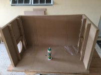
Hello, here are some shots of the build progress of one half-box, I will start to build the second one tomorrow hopefully, then start to fix edges/corners imperfections with the belt sander to close them.
Build progress log.
Hello, here are some shots of the build progress of one half-box, I will start to build the second one tomorrow hopefully, then start to fix edges/corners imperfections with the belt sander to close them.
Build progress log.
Attachments
-
 IMG_0447_Ed_Small.jpg547.3 KB · Views: 74
 -
 IMG_0445_Ed_Small.jpg506.5 KB · Views: 85
 -
 IMG_0442_Ed_Small.jpg489.1 KB · Views: 92
 -
 IMG_0439_Ed_Small.jpg490.7 KB · Views: 66
 -
 IMG_0438_Ed_Small.jpg423.1 KB · Views: 83
 -
 IMG_0436_Ed_Small.jpg442.8 KB · Views: 82
 -
 IMG_0433_Ed_Small.jpg526.9 KB · Views: 92
 -
 IMG_0429_Ed_Small.jpg352.4 KB · Views: 100
 -
 IMG_0425_Ed_Small.jpg464.9 KB · Views: 98
 -
 IMG_0412_Ed_Small.jpg404.9 KB · Views: 82
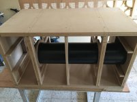
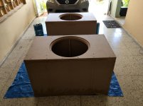
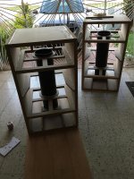
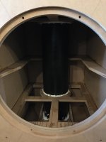
Update!
Here are some shots of the assembly progress, this things are getting indomitable due its weight though it is completely expected.😉
The finishing progress coming soon!😎
Here are some shots of the assembly progress, this things are getting indomitable due its weight though it is completely expected.😉
The finishing progress coming soon!😎
Attachments
-
 IMG_0604_Ed_Ed_Small.jpg565.9 KB · Views: 110
 -
 IMG_0591_Ed_Small.jpg529.2 KB · Views: 105
 -
 IMG_0574_Ed_Small.jpg580.6 KB · Views: 92
 -
 IMG_0550_Ed_Small.jpg533.7 KB · Views: 102
 -
 IMG_0540_Ed_Small.jpg617.7 KB · Views: 103
 -
 IMG_0539_Ed_Small.jpg503.2 KB · Views: 84
 -
 IMG_0533_Ed_Small.jpg490.2 KB · Views: 85
 -
 IMG_0532_Ed_Small.jpg469.1 KB · Views: 81
 -
 IMG_0530_Ed_Small.jpg412.5 KB · Views: 72
 -
 IMG_0608_Ed_Small.jpg448.2 KB · Views: 108
Hi thanks for the input.
After finish them and laminated I will make a new thread of the brief building progress with pictures and links, will also post my subjective impressions on how they compares with my current sealed 5FT^3 UM18-22 and add some basic REW FR measures.
After finish them and laminated I will make a new thread of the brief building progress with pictures and links, will also post my subjective impressions on how they compares with my current sealed 5FT^3 UM18-22 and add some basic REW FR measures.
- Home
- Loudspeakers
- Subwoofers
- 21" Subwoofers design suggestion