tubelab.com said:
I will post a complete schematic once I draw it up.
Thanks
Fortumately an old Volvo station wagon rides something like a big living room chair chair,........
I know what you mean. I've had 2 Volvo 265s .. very roomy !!
Andy
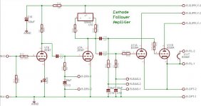
I haven't had the time to draw up the complete schematic so I am posting a screen shot of the Eagle schematic. I adjusted the component values to reflect the components that I actually used when I built the board. These may not be exactly optimum since they were based on the first available part that I could find when I decided to build the board. So far the only ones that I want to change are the 56uF caps on the bias lines. These are too large causing very slow response when adjusting.
How do you connect this board up? First up, the heater of the 6EM7's are not shown. They are connected to a 6.3V winding on the power transformer that should be biased to a small positive voltage. The 6336's each need their own floating heater winding. These tubes draw 5 amps of heater current each! As shown in the schematic each winding is tied to its respective cathode. This is to avoid H-K breakdown issues with tubes like the 5998A that has a 100 volt rating. In my testing, I simply connected each of these 3 filament connections to the filament jacks on the lab power supplies. One side of the 6EM7 winding was simply grounded.
The "R-Supply-3" terminal was connected to my Knight power supply which was maxed at 400 volts. Previous testing with the big power supply showed best results at 450 to 500 volts to insure maximum drive voltage. "R-Supply-1" and "R-Supply-2" were connected to the Fluke power supply through 10 ohm resistors so that I could monitor the current individually by connecting a $4 DVM across the resistors. I ran the 6336's at 275 - 300 volts. Higher voltages made more heat, but no more power. Other tubes will require lower voltages.
"R-DRV-1", "R-BIAS-3", and "R-BIAS-2" were each connected to a 100 K trim pot that is wired across a - 100 volt power supply. This allows individual bias adjustments from 0 to -100 volts. The OPT goes to the OPT terminals, and the input should be obvious.
I plan to design an automatic bias circuit, so I purposely left bias circuitry off of the board. A simple linear power supply is being designed also, but a SMPS is planned. All will wind up on my web site when they are finished.
Initial power up:
Set all bias pots for full -100 volts. Attach a DVM and scope (if available) to pin 2 of the 6EM7. Turn on the power supply for the driver stages (6EM7) ONLY. The voltage at pin 2 should be roughly equal to the supply at this point. Reduce the bias pot for the 6EM7 until the plate voltage comes down to about half of the supply voltage plus 30 volts. If a scope is connected, apply a signal and adjust the bias for the maximum undistorted AC voltage.
Turn on the power supply for the output tubes. SLOWLY reduce the bias voltage on one section of the 6336A until it begins to draw current. Repeat on the other section. SLOWLY raise the current on each section until the desired current is reached. I ran each section at 100 to 150 mA when I was testing one channel but I had to back this off when I ran both channels to keep my power supply from smoking!
Attachments
Conventional wisdom, and the data sheets for most of the "regulator dual triodes" ties the two grids together (with seperate stoppers) and uses individual cathode resistors of sufficient value to equalize the current through the tube sections. I have tested a bunch (hundreds) of 6AS7's and 6080's and found considerable differences between the two sections of the same tube. Some tubes require resistors in the 240 to 300 ohm range in each cathode to get the currents close. The requred resistance value rises quickly as the plate voltage is increased.
The 6336's were happy with smaller values, but this observation was based on only about 10 tubes. One tube required 100 ohm resistors for equalization. I have not done much testing with other tubes.
If resistors of this size are added in series with each cathode a considerable amount of output power will be dissipated in these resistors. The resistors would also cause the output impedance to increase. They could be bypassed with capacitors, but these capacitors would be required to pass the audio signal at currents that could approach one amp! A single capacitor wouldn't do, and any electrically good solution would be expensive.
I decided on the solution shown above to avoid individual cathode resistors. The amp has only seen about 10 hours of use with the same (very well used) 6336's installed. It has been completely stable with very little bias drift during this time. It should be noted that changes may be needed as time goes on.
I plan to design a microprocessor based biased auto bias circuit to perform bias adjustments and a few other features.
until it DOESN'T EXPLODE , then just back a littletubelab.com said:Turn on the power supply for the output tubes. SLOWLY reduce the bias voltage on one section of the 6336A until it begins to draw current. Repeat on the other section. SLOWLY raise the current on each section until the desired current is reached. I ran each section at 100 to 150 mA when I was testing one channel but I had to back this off when I ran both channels to keep my power supply from smoking!
😀
Jeb-D. said:Damn Tubelab, with all the time you spend with amplifiers how did you get so buff?😀
Take a look at his web site, and see the size of the xfmrs he uses. 😀 😀 😀
Damn Tubelab, with all the time you spend with amplifiers how did you get so buff?
The company that I have worked for the past 34 years put in a gym about 6 years ago and said that it was FREE to employees. I have been going 3 or 4 days a week for the past 5 years.
until it DOESN'T EXPLODE , then just back a little
In this case I couldn't go by the current meter since it was pegged, so I guessed (about 400 mA). After about an hour I could smell the aroma of something getting toasty inside the power supply, so I backed off a little. The power supply is a Fluke 407D that I got on Ebay for $25 (and $45 shipping). It has all of the original parts in it including the bumble bee caps, and it works pretty good. It will occasionally oscillate when subjected to these kinds of overloads, but played nice for several hours on Sunday. I suppose that I am going to feed it some new parts someday, but for now it works.
Take a look at his web site, and see the size of the xfmrs he uses.
Yeah, but the ones in this amp are tiny. The choke that I was using for the cathode weighs about 70 pounds. Now thats a transformer!
PP cathode followers
The second 1650T OPT has arrived, so it´s time to start thinking about what the rest of the circuit shall look like in my PP CF amp.
I will probably use 6S41S output tubes, the major reason is that a friend has a bunch that he is willing to trade against some iron stuff that I have.
I´m no expert on PP load lines, but it seems that 200V p-k, 140mA Ia (per side) and -75Vg will produce ~15W with a 1,9K k-k load. This requires a driver stage that can deliver 170Vrms per phase, a 12B4A LTP with an inductive plate load should manage that.
I could wire the OPT for 950R k-k and run the tubes at lower voltage and higher current but then I´d need a custom made power transformer, if I go with 200V + 75V (cathode bias) I can use a commonly available 1:1 isolation transformer and still have plenty of voltage to loose in filtering.
Another option is to wire the transformer fo 950R and use 6S33S as output tubes, with about 200V p-k they would probably produce 30-40W. 6S33S is a fairly cheap tube but they still cost money and if I decided to use them I would have to spend even more money on getting bigger filament transformers, the ones I have can handle 4x6S41S but not 4x6S33S.
Hi
For audiodesign
Why is it old projet ?
Is because it's sound not good as the investment could hope
I know the SETA
I think it's a good design
I 'd like to use 2 el519 to help the driver and obtain about 15-20W
but cost off good interstage is high +- 80€ each for Lundalh.
Yan
For audiodesign
Why is it old projet ?
Is because it's sound not good as the investment could hope
I know the SETA
I think it's a good design
I 'd like to use 2 el519 to help the driver and obtain about 15-20W
but cost off good interstage is high +- 80€ each for Lundalh.
Yan
only with the interstage transf. is possible to get enough volatge to drive output stage and low distortion
I consider this old because has been my first tube amp. and prbably with the same cost is possible to create a better project like my EL34 PSE or my last 845 amp. or my 2A3 PSE
I consider this old because has been my first tube amp. and prbably with the same cost is possible to create a better project like my EL34 PSE or my last 845 amp. or my 2A3 PSE
To answer your question, no I have not had the time to make measurements on the transformers.
The last two months have been rather hectic due to a demanding schedule at my day job, and a serious project undertaking ( a very unique cathode follower amplifier). It was submitted to this design contest:
http://www.circuitcellar.com/microchip2007/
I am sure that they have never seen anything like it, and I doubt that anything like it exists! The deadline for the contest was yesterday, and I just made it. Now I can get back to some more leisurely experimentation.
I designed a vacuum tube amplifier that uses a DSP chip to dynamically adjust the power supply voltages in real time. This can be used to drastically reduce the dissipation in the output tubes. The amplifier shown here produces about 40 watts per channel from 5998 tubes. 6AS7's will work at a slightly reduced performance. The signal path is ALL TUBE and the tubes ALL OPERATE IN CLASS A1! All tubes operate well within their ratings.
I have discovered a lot of information that I did not konw about tubes, and distortion production. I am sure that most tubeheads will never welcome a DSP powered tube amp even if it makes mad power at 1% thd and still has tube sound, but the principles that I have learned can be applied without ANY SAND!
My dissertation for the contest went over 50 pages, so I am going to take a welcome break from the computer keyboard, and then begin documentating all of this stuff for the web site. I expect that there will be some new amplifier designs based on this technology in the future, including a previously mentioned 200 WPC P-P cathode follower.
Attachments
Fuling said:My PL36 cathode follower monoblocks are almost finished, they would have been put into use days ago if I wasn´t so lazy...
Hej Fuling,
Any progress/updates on this amp? BTW, I still like the idea of a class A2 SE DHT cathode follower.
mvh,
Hej!
Unfortunately, no. For some reason the whole project just died and a couple of days ago I even took some parts from one of the monoblocks to use in another project (which can be seen in the "Edcor meets the 6AV5" thread BTW).
The remaining power transformer and the OPTs will probably become a "bedroom amp" together with a pair of EL36s and a 6SN7 or something.
The SE CF project is abandoned (for now) but the PP CF is not, a pair of LL1667/5mA plate chokes arrived earlier this week.
Together with a differential pair of 12B4As they should deliver all the swing the PL519 output stage could ever ask for.
That weird idea keeps coming back even though I´ve decided to use those tubes in a regular plate loaded amp.
AC heating obviously didn´t work so I made myself a pair of LCLC-filtered filament supplys. If I go for the CF route the PSUs must float wrt ground and follow the cathode when it swings a couple of hundred volts and I´m not sure that it would work OK.
Any progress/updates on this amp?
Unfortunately, no. For some reason the whole project just died and a couple of days ago I even took some parts from one of the monoblocks to use in another project (which can be seen in the "Edcor meets the 6AV5" thread BTW).
The remaining power transformer and the OPTs will probably become a "bedroom amp" together with a pair of EL36s and a 6SN7 or something.
The SE CF project is abandoned (for now) but the PP CF is not, a pair of LL1667/5mA plate chokes arrived earlier this week.
Together with a differential pair of 12B4As they should deliver all the swing the PL519 output stage could ever ask for.
class A2 SE DHT cathode follower
That weird idea keeps coming back even though I´ve decided to use those tubes in a regular plate loaded amp.
AC heating obviously didn´t work so I made myself a pair of LCLC-filtered filament supplys. If I go for the CF route the PSUs must float wrt ground and follow the cathode when it swings a couple of hundred volts and I´m not sure that it would work OK.
12B4A is a great little tube, I´ve used it in both line stages and as output and driver tube.
Gm is probably a bit on the low side to serve well as a cathode follower, but this is a junkbox project and I took what I had.
The output transformers are Hammond 125DSE wired as 2,5k/8 autoformers and the plate chokes for the input stages are Hammond 30H 40mA units.
D3A would probably be a better choice than E280F but again, I took what I had.
If everything goes as planned the amp will be finished tonight.
It´s finally finished, a little later than expected.
I´ve only listened to it for a couple of minutes so far but here´s the first impression:
1) Without input signal it is dead quiet!!
2) It sounds bigger/more powerful than it is.
3) The soundstage is not perfectly centered, the probable cause is unmatched input tubes. E280F is a high Gm pentode which is connected as a high µ triode and the tubes were picked randomly without matching. I´ll switch tubes between left and right channel and see what happens.
- Status
- Not open for further replies.
- Home
- Amplifiers
- Tubes / Valves
- 20W cathode follower amplifier