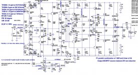
200W/8 400W/4 CFA VMOSFET
In meantime wile I am waiting for PCB for 120W CFA with lateral MOSFET here is 200W vertical MOSFET CFA.
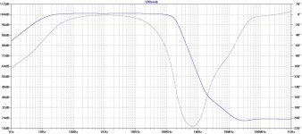
Quite low distortion, excellent Phase Margin and Gain Margin, Slew Rate 500V/usec, quite simple schematic, what to say more. To good to be true? I hope not and for sure I have to build that one. This OPS is not so expensive as the one with laterals, and does not use DC servo, just trimmer pot instead of fixed VAS emitter resistor.
RC over the VAS resistors decrease distortion (increase the loop gain) at high frequencies.
Damir
In meantime wile I am waiting for PCB for 120W CFA with lateral MOSFET here is 200W vertical MOSFET CFA.
Quite low distortion, excellent Phase Margin and Gain Margin, Slew Rate 500V/usec, quite simple schematic, what to say more. To good to be true? I hope not and for sure I have to build that one. This OPS is not so expensive as the one with laterals, and does not use DC servo, just trimmer pot instead of fixed VAS emitter resistor.
RC over the VAS resistors decrease distortion (increase the loop gain) at high frequencies.
Damir
Attachments


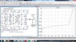
This is my attempt to plot distortion versus output voltage at 1 kHz.
If I look to .four log printout, thd_pct calculation deviate from it a bit and I am not sure way, but anyhow it is here. X axes values shown are the input voltage and if multiplied by gain of 25 it is output voltage.
Damir
If I look to .four log printout, thd_pct calculation deviate from it a bit and I am not sure way, but anyhow it is here. X axes values shown are the input voltage and if multiplied by gain of 25 it is output voltage.
Damir
Attachments
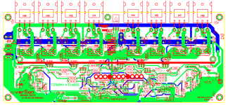
200W CFA VMOSFET
This is the version I am going to build. I have ordered all needed components and now waiting for delivery.
Here is preliminary layout, when all components arrive I will check that all fit, correct what is needed and then order the PCB production.
Damir
This is the version I am going to build. I have ordered all needed components and now waiting for delivery.
Here is preliminary layout, when all components arrive I will check that all fit, correct what is needed and then order the PCB production.
Damir
Attachments
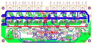
Hi Damir ,very good ,real artwork ,great layout but reverse polarity of all 4 capacitors from drain to pover ground ......🙂 also empty space left side .......
Cheers ,Alex
Cheers ,Alex
Hi Damir ,very good ,real artwork ,great layout but reverse polarity of all 4 capacitors from drain to pover ground ......🙂 also empty space left side .......
Cheers ,Alex
Thanks Alex, I knew I can't make a layout with no faults. I will check and recheck before go to production. Empty space, maybe I can put some spare transistors over there.
Cheers
Damir
Excellent in all respects, waiting for your listening reports, are you going to do Stereo?
Yes, Stereo it should be.

Looking forward to the 200W results... and, then listening to your design.
😎🙂
THx-RNMarsh


This "200W CFA VMOSFET" look very promising to me. Does it need tight matching of output mosfet (IRF240 & IRFP9240)?
This "200W CFA VMOSFET" look very promising to me. Does it need tight matching of output mosfet (IRF240 & IRFP9240)?
Some matching is needed, I am not sure how critical it is, yet, as IRFP240/9240 are not real complement.
Hi dadod, just for curiosity - why did you change design - Slewrate Fall to 250 instead of
500v/us?
Do you Think if you have two headsinks for outputstage that the Can be placed next to each other and used as one headsink?
When have you plan for 120W version with vertical mosfet?
500v/us?
Do you Think if you have two headsinks for outputstage that the Can be placed next to each other and used as one headsink?
When have you plan for 120W version with vertical mosfet?
Hi dadod, just for curiosity - why did you change design - Slewrate Fall to 250 instead of
500v/us?
Do you Think if you have two headsinks for outputstage that the Can be placed next to each other and used as one headsink?
When have you plan for 120W version with vertical mosfet?
I did not change design, this Slew rate is with input filter connected, internal Slew rate is the same.
I will do in parallel my 120W lateral and 200W vertical mosfet amps, to be sure that all worked as simulated. Than is just a question of a layout for different output power.
Thanks dadod, i really appreciate your Work🙂
according to using two headsinks for same outputstage (4 devices mounted on each heatsink) in a EF outstage you can´t make "thermal tracking" but with CFP outputstage you only monitors driver transistors?
according to using two headsinks for same outputstage (4 devices mounted on each heatsink) in a EF outstage you can´t make "thermal tracking" but with CFP outputstage you only monitors driver transistors?
Thanks dadod, i really appreciate your Work🙂
according to using two headsinks for same outputstage (4 devices mounted on each heatsink) in a EF outstage you can´t make "thermal tracking" but with CFP outputstage you only monitors driver transistors?
You are right about CFP, you have to track the drivers only, but optimum bias window is narrower and more critical. D. Self prefers CFP, but somebody said hi is back to EF now.
I don't have experience with CFB.
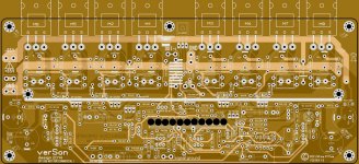
200W CFA VMOSFET
This is the layout of the PCB I am going to order prototype board tomorrow. I have all semiconductors, all elcos, most of resistors and film caps, waiting for some orders to arrive.
Happy New Years
Damir
This is the layout of the PCB I am going to order prototype board tomorrow. I have all semiconductors, all elcos, most of resistors and film caps, waiting for some orders to arrive.
Happy New Years
Damir
Attachments
Last edited:
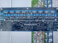
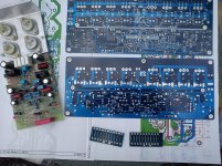
It looks that Christmas and New Year slowed the components delivery as I am still waiting for some to arrive.
Today the PCB for 200W VMOSFET amp is finished and here are the photos and the photos of 120W LMOFET soon to be tested.
Damir
Today the PCB for 200W VMOSFET amp is finished and here are the photos and the photos of 120W LMOFET soon to be tested.
Damir
Attachments
- Home
- Amplifiers
- Solid State
- 200W MOSFET CFA amp