Nattawa, I see that you are using 80V mosfets for your SSLR. You need to make sure your mosfets are at least rated for the total +- supply voltage, otherwise you run the risk of them failing (actually, its not a risk, its a certianty!). I use NXP PSMN4R4-100 for +-50V rail, and Fairschild 150V types for up to +-75V rails (I forget the part number). The pinouts are the same - TO-220. Both of these types can switch 10's of amps if you do it quickly. There are two articles on my website with the details to help you select the SSLR mosfets.
Nice board by the way - complex circuit though!
🙂
Thanks Bonsai! I copy-pasted it from a 50W amp and didn't bothered the MOSFET datasheet. You're absolutely right, I'll put Fairchild FDP075N15A 150V rated devices instead.
Nattawa
I am not going to go out and buy SMT devices to do this or any project. IF it where in kit form, I might consider it. IF the pads are the same size, why not have a hole in them to put a regular axial lead resistor and or capacitor. In other words why do SMT just for the sake of doing SMT.
I have have some SMT in one flavor, I wanted to do OPS emitter resistors non inductive. That "might" be my venture into SMT land. I wish you luck on doing your board and I hope it works for you.
Dadod
I am keeping the faith, I am dyed in wool, you are a leader and innovator of this topology and I am just trying to be a part of the effort to help advance that.
But I want to see what OS is doing with all that is on the table, the EDN article is a path I want to pursue TOO. Then I can compare and enjoy. I want to incorporate some digital input and power control using Arduino. My expertise is in digital by a factor of 10 to 1 over my analog. Maybe this old dog can learn a few tricks before I can not hear the music or see the SMT chips I am trying to solder on a board. I built my first slug tuned radio at seven right after the crystal tuned one with a safety pin one touching the crystal in the third grade. The first tube thing I built used batteries...
Last edited:
Kris, I design the board for myself and share it with anyone in the forum who are interested in or willing to do SMT. It does not surprise me if SMT is not your thing or that of anyone else.
The question can be put the other way around. Why put holes in a PCB when SMT parts do the job just as well or better while offering smaller size, ease of soldering and reworking, cheaper in price, much more flexibility in layout design, more predictable and controllable parasitic parameters.....?
.........IF the pads are the same size, why not have a hole in them to put a regular axial lead resistor and or capacitor. In other words why do SMT just for the sake of doing SMT.
The question can be put the other way around. Why put holes in a PCB when SMT parts do the job just as well or better while offering smaller size, ease of soldering and reworking, cheaper in price, much more flexibility in layout design, more predictable and controllable parasitic parameters.....?
Kris, I design the board for myself and share it with anyone in the forum who are interested in or willing to do SMT. It does not surprise me if SMT is not your thing or that of anyone else.
The question can be put the other way around. Why put holes in a PCB when SMT parts do the job just as well or better while offering smaller size, ease of soldering and reworking, cheaper in price, much more flexibility in layout design, more predictable and controllable parasitic parameters.....?
Because I can see and read the color codes on the resistors easier than I can see the resistor values on the SMT resistors.😀 Just wait till you get older...😉
Because I can see and read the color codes on the resistors easier than I can see the resistor values on the SMT resistors.😀 Just wait till you get older...😉
Sounds like all you need is a big magnifying glass and some tweezers. In all seriousness though 0805 and larger resistors are IMHO just as easy to solder as through holes.
Can you send me some color coded ones or tell me where I can get them on Ebay.Sounds like all you need is a big magnifying glass and some tweezers. In all seriousness though 0805 and larger resistors are IMHO just as easy to solder as through holes.
I have a dental chair type magnifying glass with 2 lights and I prefer forceps to tweezers for my geezers shaky hanks.😱
Attachments
Last edited:
Smd capacitors don't have any codes on them.Because I can see and read the color codes on the resistors easier than I can see the resistor values on the SMT resistors.😀 Just wait till you get older...😉
Many are the same size and the same colour, even for different types.
Has anyone seen the ad for prototype PCB's that will make 2 for 25 dollars each? Or maybe a better offer.
All of the caps I have in bulk I can easily ID by color size and shape and I can bin those of the type I am working on a project for. Usually it is the comp caps that have to be put up, the filters not so much difficulty... live and learn.
http://www.ebay.com/itm/Transistor-...380?pt=LH_DefaultDomain_0&hash=item1c371cc034
I am going to get this to make sure I get the right part on the board, this is a good and quick check of what I am doing, checks every part, just before mounting.
Last edited:
Can you send me some color coded ones or tell me where I can get them on Ebay.
@ Krisfr
These MELF Resistors were quite reliable and survive very hard vibrational, thermal and heavy overload tests, we used them quite extensively and might be also useful for audio purposes,
they are color coded . . .
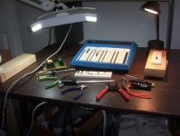
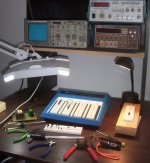
Nice Mag. Lamp You have there 🙂
Btw, I have same sighting problems as You, could You provide some more details about Yours magnifying lamp, manufacturer, type, a link to the product would be much appreciated, thnx for the info in advance . . .
Cheers,
Andreas
Attachments
@ Krisfr
These MELF Resistors were quite reliable and survive very hard vibrational, thermal and heavy overload tests, we used them quite extensively and might be also useful for audio purposes,
they are color coded . . .
Nice Mag. Lamp You have there 🙂
Btw, I have same sighting problems as You, could You provide some more details about Yours magnifying lamp, manufacturer, type, a link to the product would be much appreciated, thnx for the info in advance . . .
Cheers,
Andreas
Amazon.com - Ultra-Efficient 108 LED Magnifier Lamp - Large 7" x 6" Lens 5-Diopter
I had ordered the LED one but they shipped me one with florescent bulbs, it is okay, they refunded me a good amount to avoid shipping 3 times. I still use LED lamps in addition to the ones seen. The glass is not great but it works. Shop for it on ebay or amazon I only paid about 40 dollars, but it has been a while. Good luck with that.
I think that might be an answer for the resistors for me. Like I said I am going to use the digital display to verify the caps and axial lead resistors before I mount them on the boards. Makes life simpler. 😱 for my well used eyes. I still have 20 20 with corrective lens. Can drive at night without problems still. But one day...😉
Hi Krisfr,
Thank You for the info, I found the Lamp and also read the comments....
So You if latter add that led Lamps to Yours Mag Lamp with florescent bulbs, You got a better product anyway ... 🙂
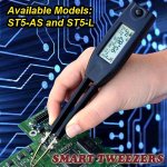
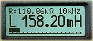
I do have to work all the time with this tinniest SMDs little critters and a while back for this same reason I buy a Smart Tweezers so I can quick measure even within the PCB boards almost all SMD Parts from R, L, C, and can easily read Big Numbers on LCD too. 🙂
The Precision is also very good and selecting the little critters is very easy and fast. If It is needed to measure a bigger Elcos or Resistors simply make an detachable 10 cm extension cable clips and You're done.
Just hover with mouse over blue txt and click on it ..... Then Read ....
I can only highly recommend them to You also, for me they are the indispensable . . . .
Cheers 😉
Some Quick Specs:
--------------------------------
ACCURACY SPECIFICATION for Resistance, Capacitance and Inductance RangesParameter Measurement Range Basic Measurement Accuracy*
Resistance 1Ω to 999 kΩ < 0.2%
0.1 to 9.9 MΩ < 0.5%
Capacitance 10 pF to 100 μF < 0.5%
0.5 pF to 999 μF < 1.0%
Inductance 10 μH to 99 mH < 0.5%
0.5 μH to 999 mH < 1.0%
* at optimum test frequency, ranges, without calibration offset
Typical offsetResistance ≤ 25 mΩ
Capacitance 0.65 pF
Inductance 0.1 uH
Offset value should be subtracted from measurement result for small value components (R < 10Ω, C < 100 pF, L < 10 μH).Parameter Measurement Range Test frequency
Resistance < 9.9 MΩ 1 kHz
Capacitance < 9999 pF 10 kHz
10000 pF to 1 μF 1 kHz
> 1 uF 100 Hz
Inductance 0.5 μH to 99 μH 10 kHz
100 μH 99 mH 1 kHz
> 100 mH 100 Hz
Maximum measurement rangesResistance R 0.05 Ω to 9.9 MΩ
Capacitance C 0.5 pF to 999 μF
Inductance L 0.5 μH to 999 mH
Quality factor Q 0.001 to 1000 *
Dissipation factor D 0.001 to 1000 *
Maximum resolutionImpedance/Resistance Z or RAC 10 mΩ
Capacitance C 0.1 pF
Inductance L 0.1 μH
Quality factor Q 0.001
Dissipation factor D 0.001
Thank You for the info, I found the Lamp and also read the comments....
So You if latter add that led Lamps to Yours Mag Lamp with florescent bulbs, You got a better product anyway ... 🙂
I do have to work all the time with this tinniest SMDs little critters and a while back for this same reason I buy a Smart Tweezers so I can quick measure even within the PCB boards almost all SMD Parts from R, L, C, and can easily read Big Numbers on LCD too. 🙂
The Precision is also very good and selecting the little critters is very easy and fast. If It is needed to measure a bigger Elcos or Resistors simply make an detachable 10 cm extension cable clips and You're done.
Just hover with mouse over blue txt and click on it ..... Then Read ....
I can only highly recommend them to You also, for me they are the indispensable . . . .
Cheers 😉
Some Quick Specs:
--------------------------------
ACCURACY SPECIFICATION for Resistance, Capacitance and Inductance RangesParameter Measurement Range Basic Measurement Accuracy*
Resistance 1Ω to 999 kΩ < 0.2%
0.1 to 9.9 MΩ < 0.5%
Capacitance 10 pF to 100 μF < 0.5%
0.5 pF to 999 μF < 1.0%
Inductance 10 μH to 99 mH < 0.5%
0.5 μH to 999 mH < 1.0%
* at optimum test frequency, ranges, without calibration offset
Typical offsetResistance ≤ 25 mΩ
Capacitance 0.65 pF
Inductance 0.1 uH
Offset value should be subtracted from measurement result for small value components (R < 10Ω, C < 100 pF, L < 10 μH).Parameter Measurement Range Test frequency
Resistance < 9.9 MΩ 1 kHz
Capacitance < 9999 pF 10 kHz
10000 pF to 1 μF 1 kHz
> 1 uF 100 Hz
Inductance 0.5 μH to 99 μH 10 kHz
100 μH 99 mH 1 kHz
> 100 mH 100 Hz
Maximum measurement rangesResistance R 0.05 Ω to 9.9 MΩ
Capacitance C 0.5 pF to 999 μF
Inductance L 0.5 μH to 999 mH
Quality factor Q 0.001 to 1000 *
Dissipation factor D 0.001 to 1000 *
Maximum resolutionImpedance/Resistance Z or RAC 10 mΩ
Capacitance C 0.1 pF
Inductance L 0.1 μH
Quality factor Q 0.001
Dissipation factor D 0.001
Attachments

Smiley
Thanks ever so much, I have been exposed to New High Technology, my mind can never go back to Simpson 260's...
I see ( pun intended) that I am not the only one with eye strainist. You can teach an OLD dog new tricks even in Electronics. My Self Christmas Budget is over limit some more.
Thanks ever so much, I have been exposed to New High Technology, my mind can never go back to Simpson 260's...
I see ( pun intended) that I am not the only one with eye strainist. You can teach an OLD dog new tricks even in Electronics. My Self Christmas Budget is over limit some more.
Because I can see and read the color codes on the resistors easier than I can see the resistor values on the SMT resistors.😀 Just wait till you get older...😉
same for me... weakening eye sight.... I have not yet made anything with SMD... probably never will as I am not getting younger.
Thx-Richard Marsh
same for me... weakening eye sight.... I have not yet made anything with SMD... probably never will as I am not getting younger.
Thx-Richard Marsh
Hi Richard,
You showed interest in this pre amp before, are you still interested in the PCB, no SMT used? Tell me what you think of this: http://www.diyaudio.com/forums/solid-state/235695-no-nfb-line-amp-gainwire-mk2-22.html#post3745448
BR Damir
Dadod
Am I correct to assume the Q11 and Q12 need to be beta matched and thermally coupled? Any other matching and coupling on the board?
Also would it do any good to put a PGA2310 volume control on your preamp?
Am I correct to assume the Q11 and Q12 need to be beta matched and thermally coupled? Any other matching and coupling on the board?
Also would it do any good to put a PGA2310 volume control on your preamp?
Has anyone seen the ad for prototype PCB's that will make 2 for 25 dollars each? Or maybe a better offer.
Dadod
Am I correct to assume the Q11 and Q12 need to be beta matched and thermally coupled? Any other matching and coupling on the board?
Also would it do any good to put a PGA2310 volume control on your preamp?
The Q11 and Q12 are better if beta matched, but I thermally coupled Q11 with Q3 and Q12 with Q4, but it is not so importand as disipation of those transistors is quite low.
PGA2311(not PGA2310 it is 5 V version) is other thing completely, if you use it you don't need my preamp as this chip has enough gain to be use alone(with a buffer if you want to drive a phones).
But this is not what I want here, no global negative feeback, or CFA.
I used Chinese remote volume with PGA2311 in the amp I made for my daughter(display led backlight died soon, be careful were you buy) and it works😀
Hi Richard,
You showed interest in this pre amp before, are you still interested in the PCB, no SMT used? Tell me what you think of this: http://www.diyaudio.com/forums/solid-state/235695-no-nfb-line-amp-gainwire-mk2-22.html#post3745448
BR Damir
Yes, of course I am still interested. All very good stuff. 🙂
Interested in 200W and line level, both.
Thanks, Richard Marsh
Last edited:
Hi Richard,
You showed interest in this pre amp before, are you still interested in the PCB, no SMT used? Tell me what you think of this: http://www.diyaudio.com/forums/solid-state/235695-no-nfb-line-amp-gainwire-mk2-22.html#post3745448
BR Damir
yes. Very interested. I would like to get one to listen to. 🙂
Thx-Richard Marsh
Last edited:
yes. Very interested. I would like to get one to listen to. 🙂
Thx-Richard Marsh
I will order a few GainWire-mk2 PCBs and I can send one(it is two channels with power supply) to you, but you have to staff and test it, if this is OK with you?
For 200W CFA we have to wait for Krisfr to give as some result.
BR Damir
- Home
- Amplifiers
- Solid State
- 200W MOSFET CFA amp