10nf , 22nf , 47nf , 100nf , 220nf and so on up to 1uf
in parralele with 8R and 4R , signal being 10Khz starting
the test from a few volts up to close to clipping.
Speeds are on the 30-50V/us since i figured long ago
that linearity and speed are two different matters that
are not mutualy tradable , i.e , more speed cant and will
never compensate for lack of linearity , that s what i concluded
after examining and simulating scores of amplifiers designed
by japaneses engineers who did test all that is possible in commercial
and functional designs.
10nf , 22nf , 47nf , 100nf , 220nf and so on up to 1uf
in parralele with 8R and 4R , signal being 10Khz starting
the test from a few volts up to close to clipping.
Speeds are on the 30-50V/us since i figured long ago
that linearity and speed are two different matters that
are not mutualy tradable , i.e , more speed cant and will
never compensate for lack of linearity , that s what i concluded
after examining and simulating scores of amplifiers designed
by japaneses engineers who did test all that is possible in commercial
and functional designs.
I hope that you don't expect that all those capacitances an amp should withstand with no output inductor?
I would go down to 100p and also into clipping.10nf , 22nf , 47nf , 100nf , 220nf and so on up to 1uf
in parralele with 8R and 4R , signal being 10Khz starting the test from a few volts up to close to clipping.
IME, the most difficult loads are between 1n & 10n.
I've also done loadsa theoretical & 'real life' work on this which suggests you can't design, as opposed to fudge, a power amp to be unconditionally stable with load without an output inductor network.
Some important points aren't obvious. eg you need to have electrolytics on the rails AT the output/VAS/IPS devices. You can have Golden Pinnae films on the rails too but DON'T LEAVE OUT THE ELECTROLYTICS
Tian probe for just OPS ULGF on 'symmetrical' amps?
I put one between the OPS emitter resistors (vout) and the feedback take off point R47 ie where dadod has his. But I think that looks at LG for the whole amp.
Dave, where do you place the Tian probe to look at just OPS ULGF on these evil 'symmetrical' amps?I checked your ASC from post #74 and found the OPS ULGF is just a bit more than 19 Mz.
I put one between the OPS emitter resistors (vout) and the feedback take off point R47 ie where dadod has his. But I think that looks at LG for the whole amp.
...where do you place the Tian probe to look at just OPS ULGF on these evil 'symmetrical' amps?...
In the feedback loop between the output node and BEFORE the next node splits the feedback to two different destinations.
That should be equivalent to the Return Ratio measured at the input to the OPS, but much easier to do.
Best wishes
David
Hi everyone,
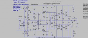
That design seems very interesting, nice work dadod 😉
It's possible to use it with the BUZ900/905 pair and raise the voltage gain to 30 dB? 😀
I only need one half of that power (100W/8R - 200W/4R)
I like to make a design similar to this one, but I don't know anything about CFA toplogy amplifiers 🙁
CFA amplifiers could use TMC compensation scheme?
Best regards,
Daniel
Hi everyone,
That design seems very interesting, nice work dadod 😉
It's possible to use it with the BUZ900/905 pair and raise the voltage gain to 30 dB? 😀
I only need one half of that power (100W/8R - 200W/4R)
I like to make a design similar to this one, but I don't know anything about CFA toplogy amplifiers 🙁
CFA amplifiers could use TMC compensation scheme?
Best regards,
Daniel
Daniel, you can use a half of the OPS .asc files you can find in previous posts. You can use Cordell's models instead BUzxx, I think they are similar.
BINGO..O!In the feedback loop between the output node and BEFORE the next node splits the feedback to two different destinations.
That should be equivalent to the Return Ratio measured at the input to the OPS, but much easier to do.
Guru Zan, you've provided me with the missing tool for designing as opposed to fudging CFAs. Many thanks!
Er.rrh! Still need a way of doing Loop Gain for complete Simple CFAs. Damn! 😡
But evil diamonds are no problem now. 😀
...
Guru Zan, you've provided me with the missing tool for designing as opposed to fudging CFAs. Many thanks!
It's a pleasure. So I won't post the explanatory pictures I promised unless there is a request.
Still need a way of doing Loop Gain for complete Simple CFAs.
What's the problem?
Best wishes
David
I hope that you don't expect that all those capacitances an amp should withstand with no output inductor?
Not difficult but surely not possible without seriously
reconsidering the THD and slew rate numbers.
I've also done loadsa theoretical & 'real life' work on this which suggests you can't design, as opposed to fudge, a power amp to be unconditionally stable with load without an output inductor network.
It can be made but not with the extravagant high frequency
loop gains that we can see here and there.
I hope that you don't expect that all those capacitances an amp should withstand with no output inductor?
wahab said:Not difficult but surely not possible without seriously
reconsidering the THD and slew rate numbers.
I've also done loadsa theoretical & 'real life' work on this which suggests you can't design, as opposed to fudge, a power amp to be unconditionally stable with load without an output inductor network.
Wahab, what about YOUR designs?Not difficult but surely not possible without seriously reconsidering the THD and slew rate numbers.
Are the criteria in #101 what you strive for? What THD figures can you achieve with these restrictions?
___________________
Still need a way of doing Loop Gain for complete Simple CFAs.
IMveryHO, you need to look at both the inner loop(s) AND Loop Gain for the whole amp. Like Bob, I believe (and have some limited 'real life' evidence of this,) each encompassing loop will also show problems in any inner loops.Dave Zan said:What's the problem?
Hence if you want a single PM/GM figure, you should use the Loop Gain for the whole amp (though I ALWAYS look at inner loops too) The inner VAS + OPS + Cherry loop is in fact what you maximise with NDFLs so its no surprise that my naive version also has zillion GHz ULGF. 🙂
The problem is a Tian probe for the whole amp is easy with evil VFAs & diamond CFAs .. but I can't figure out how to do this for simple CFAs 😡
___________________
Last edited:
The problem is a Tian probe for the whole amp is easy with evil VFAs & diamond CFAs .. but I can't figure out how to do this for simple CFAs
You mean because the of the parallel feedback paths?
Search for P J Hurst to see how to do this.
Best wishes
David
Yes. As in VSSA or my #500 input stageYou mean because the of the parallel feedback paths?
Any more clues? I've searched P J Hurst, PJ Hurst, Hurst PJ and various other combinations without success.Search for P J Hurst to see how to do this.
Last edited:
Yes. As in VSSA or my #500 input stage
Any more clues? I've searched P J Hurst, PJ Hurst, Hurst PJ and various other combinations without success.
Surprised it didn't show up.
This link Return Ratio simulation should provide a few ideas and let you find the full text.
It's not exactly what you want but probably adaptable.
Otherwise I'll think about it.
Best wishes
David
Last edited:
A very nice test for stability is to combine an LF sine wave signal of a few hundred Hz with a square wave of about 20 KHz. The square wave should be about 2-3 % of the amplitude of the sine wave. Drive the amp close to clipping ( so full power ) and then look at the square wave - in a well comp'd amp, AND one that is not suffering from parasitics, you should get a nice clean square wave with no overshoot at any point on the sine wave.
The idea of the large signal sine wave is that you are exercising all the transistors over a wide dynamic range, whilst still observing the loop performance - and you can tell a lot from an amps square wave response. The TIS stage and the output stage device parametrics change markedly with Vce and Ic. This test checks for almost all of those conditions.
One of the things that happens to amplifiers that suffer excessively y from 'parametric modulation' is that at the voltage peaks, or just after exiting clipping, they burst into HF oscillation and then recover a little further align the sine wave. Often this has nothing to do with loop stability, but the fact that the TIS and output devices gain, Ft and Cob are significantly different compared to their values closer to 0 V.
For this test, the load should be resistive, and then after that you can try capacitive etc. and then clipping recovery performance.
Harry Dymond shows this technique in his TPC paper, but the originator was a guy from the 60 s or 70 's who's name I cannot recall right now.
Solid, practical engineering - I love it!
😎
Last edited:
R.C. Bowes (WW Dec 1962)
Brian.
Thanks for that!
Lets call it the 'Bowes Test' or BT for short - it's a great test in the amplifier designers toolbox.
The problem is a Tian probe for the whole amp is easy with evil VFAs & diamond CFAs .. but I can't figure out how to do this for simple CFAs
As in... my #500 input stage
Ok. I've had a think, skip Dr Hurst, I can do this myself.
Post the ASC for #500 and I will demonstrate.
Best wishes
David
Last edited:
- Home
- Amplifiers
- Solid State
- 200W MOSFET CFA amp