Ah okay. I think it was my 50W design that did 1e-6% 1K full power. If I remember correctly, the 250W 8 Ohm was 2 or 3e-6%.But that was at 100W or 200W for powerful version.
Ah okay. I think it was my 50W design that did 1e-6% 1K full power. If I remember correctly, the 250W 8 Ohm was 2 or 3e-6%.
My TT amp(VFA) simulates 3e-6% 1k at 100W 8 ohm.
edit: it looks like "my is smaller then yours" 😀
Last edited:
Would you agree the outputstage and compensation used are the decisive factors in a negative feedback poweramp design?
Yes, but don't forget distortion at 1 kHz .000001%, I never seen that in VFA amp simulation.
This means that if OLG THD1 is 0.1% then 100db NFB
are to be available to reach such a number....
A lateral fet OPS has about 0.2-0.5% THD depending
of the number of parralleled devices.
Last edited:
Would you agree the outputstage and compensation used are the decisive factors in a negative feedback poweramp design?
Technically I would and I like my TT VFA amp a lot. What is behind the magic of CFA amp I don't know as I never built one but I am intrigued.
My TT amp(VFA) simulates 3e-6% 1k at 100W 8 ohm.
edit: it looks like "my is smaller then yours" 😀
Talking about values, can you attach some pictures?
Talking about values, can you attach some pictures?
If you want to see some picture of my TT VFA amp here is whole thread about it. http://www.diyaudio.com/forums/solid-state/182554-thermaltrak-tmc-amp.html
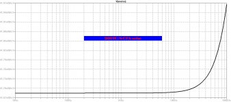
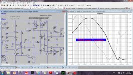
Some people are interested in more powerful CFA amp, and this is 200W//8ohm and 400W//4ohm....
Damir,
Can you add a noise sim to this (please 🙂).
Damir,
Can you add a noise sim to this (please 🙂).
There is no difference in the noise between 200W//8ohm and 400W//4ohm.
Attachments
LOL yeah.. I may need to compensate my THD with brute heatsink size!edit: it looks like "my is smaller then yours" 😀
LOL yeah.. I may need to compensate my THD with brute heatsink size!
That's the price we all pay. 🙂
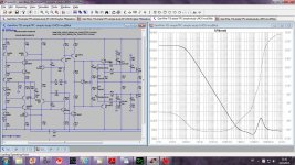
How good is PSRR for this amp and how could be improved in quite simple way. I simulated tree different cases, no any aditional power line filtering, simple RC filter for input stage only, and simple C multiplier for input stage. All this was simulated on + power line only, - line PSRR should show similar results.
BR Damir
BR Damir
Attachments
After restoring my Adcom 535, building a chip amp, currently working on Richard Marsh's headphone amp, and using the LME49713, I am really hoping you guys come up with something beautiful here for my first big amp project. I'll just sit here and quietly lurk and learn. 😉
Dadod,
You are a mind reader. last night I was thinking about asking you about PSRR.
Would you be able to do similar sims for the simpler (lower LG) version. It would be interesting to see how/if LG affects PSRR.
Thanks
Paul
You are a mind reader. last night I was thinking about asking you about PSRR.
Would you be able to do similar sims for the simpler (lower LG) version. It would be interesting to see how/if LG affects PSRR.
Thanks
Paul
Dadod,
You are a mind reader. last night I was thinking about asking you about PSRR.
Would you be able to do similar sims for the simpler (lower LG) version. It would be interesting to see how/if LG affects PSRR.
Thanks
Paul
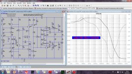
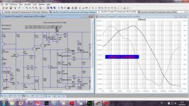
PSRR lower LG version.
Attachments
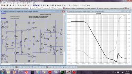
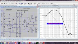
Thank you. It shows some minor benefits to the added complexity for the higher LG version. Although these are only at low frequency.
The cap multiplier looks like a easy win. The complexity is minimal and the extra voltage drop could be countered by a small dual secondary transformer added to the main PSU transformer.
The cap multiplier looks like a easy win. The complexity is minimal and the extra voltage drop could be countered by a small dual secondary transformer added to the main PSU transformer.
dadod, you need to use real world cap models to assess PSRR.
I used LTspice capacitance models, changed ESR and ESL and no any significant differences showed. Tell me what real world cap model you suggest?
Thank you. It shows some minor benefits to the added complexity for the higher LG version. Although these are only at low frequency.
The cap multiplier looks like a easy win. The complexity is minimal and the extra voltage drop could be countered by a small dual secondary transformer added to the main PSU transformer.
JLH in his 80W mosfet amp used +-55V for OPS and +-50V for input stage not to saturate lateral mosfet when they go in very unlinear input capacitance(if I remember it correctly) so small voltage drop(1.2V) on the C multiplier is OK for me.
- Home
- Amplifiers
- Solid State
- 200W MOSFET CFA amp