I have a little concern about the gate protection zener diodes that, in an unfortunate event of output being shorted to GND, there could be large current going through them as well as through the driver transistors that may result in these devices being driven beyond their maximum limits and getting destroyed. Could this be a real issue?
I suggest to use my power supply with cap multiplier and all needed protection like I used in my TT amp, but with higher voltage of course.
BR Damir
Attachments
... use my power supply with cap multiplier and all needed protection like I used in my TT amp...
Damir this PSU looks too much like a VFA.😉
I am sure someone will say you can't use a complementary LTP in a CFA amp.
You must make a CFA front end for the PSU.
Best wishes
David
Damir this PSU looks too much like a VFA.😉
I am sure someone will say you can't use a complementary LTP in a CFA amp.
You must make a CFA front end for the PSU.
Best wishes
David
David, but then here is the best combination of both worlds. I hope it will put some peace between two confronted parties.

BR Damir
Last edited:
I suggest to use my power supply with cap multiplier and all needed protection like I used in my TT amp, but with higher voltage of course.
BR Damir
Is there a layout for this schematic?
Is there a layout for this schematic?
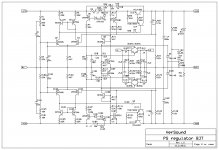
This is the layout for presented regulator schematic but this is enough for 100 W amp.
For 200 W amp input voltage for the regulator shoud be increased to +- 70 to 75 V, resistors R23 and R123 changed to 20 Kohm, and output serial transitors doubled or even tripled(Q13, Q113).
BR Damir
Attachments
![PSregulator-BJT-c.LAY].jpg](/community/data/attachments/355/355823-f5a92799351aadfd8b0cd85412072499.jpg?hash=9aknmTUarf)
I suggest to use my power supply with cap multiplier and all needed protection like I used in my TT amp, but with higher voltage of course.
BR Damir
How would you arrange this PS circuit into a +/- tracking regulator. Seems just a few changes are all that is needed. Tracking or MS (Master-Slave) regulators are much better for power amplifiers. IMO.
Thx-RNmarsh
How would you arrange this PS circuit into a +/- tracking regulator. Seems just a few changes are all that is needed. Tracking or MS (Master-Slave) regulators are much better for power amplifiers. IMO.
Thx-RNmarsh
If I cross connect feedback resistors to the oposite polarity instead to the ground then a +/- tracking is better but not much. Could you give me a hint how to make better tracking?
BR Damir
Can I propose a PCB layout based on 0805 and larger SMT passive parts? The much smaller size of the components allows for a compact placement, and I was able to put in a high frequency local Zobel network per individual MOSFET. I haven't had a chance to simulate it yet.
The PCB has a size of 202x79 mm^2, it conveniently accommodates a solid state speaker relay fired by a photo voltaic device under the control of a DC detection circuit. An external 12VDC supply is needed for the relay. This relay circuit can be opted out by shorting out two solder jumpers.
In the upper left corner of the layout, a breakaway piece carries the feedback resistor chain. This part can be attached as a daughter card on the bottom side of the main PCB where the output inductor and the star GND connector sit with two 2-conductor pin headers.
Electrolytic caps for the OPS has footprint for either 16mm DIA (1000uF/100V) or 22mm DIA (3300uf/80V).
Attachments
Can I propose a PCB layout based on 0805 and larger SMT passive parts? The much smaller size of the components allows for a compact placement, and I was able to put in a high frequency local Zobel network per individual MOSFET. I haven't had a chance to simulate it yet.
The PCB has a size of 202x79 mm^2, it conveniently accommodates a solid state speaker relay fired by a photo voltaic device under the control of a DC detection circuit. An external 12VDC supply is needed for the relay. This relay circuit can be opted out by shorting out two solder jumpers.
In the upper left corner of the layout, a breakaway piece carries the feedback resistor chain. This part can be attached as a daughter card on the bottom side of the main PCB where the output inductor and the star GND connector sit with two 2-conductor pin headers.
Electrolytic caps for the OPS has footprint for either 16mm DIA (1000uF/100V) or 22mm DIA (3300uf/80V).
I am impressed with your skill, very nice layout and then with SMT.
I would like to suggest something:
1. Insert input polypropylene cap in the input, 1 uF is high enough value.
2. Insert a trim pot of 200 ohm parallel to the R15, R23, then change those resistors from 15 ohm to 18 ohm, this to trim output DC offset.
3. Q5 and Q6 should be for higher voltage as almost all power supply voltage is on them.
4. Q11 and Q16 should have own smal heath sinks as thy dissipate 1.7 W max.
5. Q17, Q20, Q22 and Q23 should also have own small heath sinks, max dissipation 1.2 W.
6. Electrolytic caps for the OPS don’t need to be of so high value, max 1000 uF is more then enough.
7. Resistors R51 and R52 use 33 ohm instead 82 ohm.
8. Put one jumper between R42 and R46 midle point and feedback input point, in this way one can decide to use high or low feedback and decide by listening the preference.
9. R88(R9 in my schematic) should be of 1 W.
I did not look to carefully the layout, but I like the name(Meistersinger after Wagner opera??) and will be nice if you add my name as designer.
It will be very exiting to compare this SMT layout and trough the hole one that Chris will present soon.
BR Damir Verson
Last edited:
Would not think that my reg is better performing than yours considering your more compilicated cktCould you give me a hint how to make better tracking?
I proposed one and got zero feedback when I posted it. No where as complicated as yours but it does have short circuit protection. Still learning ltspice, so have to figure out how to measure PSRR etc.
http://www.diyaudio.com/forums/powe...-high-v-tracking-linear-regulator-review.html
Since you want single sided (cost?), not sure if you are using SM. If you are, leave a SM opening that follows the trace, this allows for solder to be added, either by hand or during the wave solder operation. Many have done this in the past.
Would not think that my reg is better performing than yours considering your more compilicated ckt
I proposed one and got zero feedback when I posted it. No where as complicated as yours but it does have short circuit protection. Still learning ltspice, so have to figure out how to measure PSRR etc.
http://www.diyaudio.com/forums/powe...-high-v-tracking-linear-regulator-review.html
Thank you for that, I havn't seen this one and I have to look how to implement that tracking in my regulator.
......I would like to suggest something:
1. ~~~ 9.
BR Damir Verson
Thanks for the feedback, dadod. I'll look into all your suggestions. Sorry for leaving you name out by accident, my bad ~~ I borrowed the layout from another Meistersinger (a VFA) I am working on that has the similar OPS and solid state relay layout. And yes, it was after Wagner's opera. This year happens to be his 200th birth anniversary.
All mfr of volt regulator IC make tracking volt reg. Even if just a pair of 3-terminal volt reg are used, they can be operated as tracking -->
View attachment 3 term reg as tracking.pdf
Check it out and give it a try.
Thx-RNMarsh
View attachment 3 term reg as tracking.pdf
Check it out and give it a try.
Thx-RNMarsh
Would not think that my reg is better performing than yours considering your more compilicated ckt
I proposed one and got zero feedback when I posted it. No where as complicated as yours but it does have short circuit protection. Still learning ltspice, so have to figure out how to measure PSRR etc.
http://www.diyaudio.com/forums/powe...high-v-tracking-linear-regulator-review.html
All mfr of volt regulator IC make tracking volt reg. Even if just a pair of 3-terminal volt reg are used, they can be operated as tracking -->
View attachment 380765
Check it out and give it a try.
Thx-RNMarsh
Here is Power Supply Regulator with tracking similar to rsavas design(tracking part). I tried first what I thought could improve the tracking(cross connection of the feedback resistor) and the result was better than with no tracking but not much improved. Than I simulated Richard suggestion and still I did not get satisfactory result, so I tried rsavas master slave approach and here is the simulation. To simulate how good tracking is I introduced a current pulses in the positive and negative side with quite low frequency of 3 Hz. With normal music current fluctuation(AB class amp) it should behave even better.
BR Damir
Attachments
Is there any way of posting a picture here with out using the built in upload system?
🙁 I am not able to post a pic of the board I am working on.
🙁 I am not able to post a pic of the board I am working on.
More High-End Design secrets -
Great! This is a new chapter in PS for audio... it should catch on. Better late than never. Been using it myself for decades. No matter if it is a series regulator or parallel/shunt/push-pull (my favorite introduced in the 1980's in an article I did in TAA) the importance of keeping the dynamic DELTA of V+ and V- at a minimum is key to best performance.
Thx-RNMash
Than I simulated Richard suggestion ...
To simulate how good tracking is I introduced a current pulses in the positive and negative side with quite low frequency of 3 Hz. With normal music current fluctuation(AB class amp) it should behave even better.
BR Damir
Great! This is a new chapter in PS for audio... it should catch on. Better late than never. Been using it myself for decades. No matter if it is a series regulator or parallel/shunt/push-pull (my favorite introduced in the 1980's in an article I did in TAA) the importance of keeping the dynamic DELTA of V+ and V- at a minimum is key to best performance.
Thx-RNMash
Last edited:
High-End design secrets -
Here is something you can try as a SIM..... I first suggested this about 15 years ago to Brian Elliot (PhD EE -Stanford) and it has been introduced a few years ago commercially and is starting to catch on... has been even accepted by other design experts such as D.Self.
Conceptual development -- Take a standard unreg circuit..... with 10,000 mfd filter on each supply + and - to ground. Then bridge a 10,000mfd cap across the + and -. Do sim on it under dynamic loading like you did on your tracking reg.
Thx-RNMarsh
Last edited:
Here is something you can try as a SIM..... I first suggested this about 15 years ago to Brian Elliot (PhD EE -Stanford) and it has been introduced a few years ago commercially and is starting to catch on... has been even accepted by other design experts such as D.Self.
Conceptual development -- Take a standard unreg circuit..... with 10,000 mfd filter on each supply + and - to ground. Then bridge a 10,000mfd cap across the + and -. Do sim on it under dynamic loading like you did on your tracking reg.
Thx-RNMarsh
Sorry to say that but my simulation shows no different what's so ever with and wihtout a cap across + and -. I simed with 10 Hz and 100 Hz of dynamic loading.
There is still problem with picture upload so I can't upload my simulations, could be that I simulate wrongly.
BR Damir
Guys, when I was working on dual HV reguaktor, I first though of using LM317/337, but going above 37V meant I had to have extra ckt for short circuit.
Richard, I am a bit unclear as well, I know I am hard at learning, need a hammer some times.
Have you noticed TI tps7a33 & tps7a4700-01-02?
Basically my ckt is a academic exercise, use these above and a external current limiter if o/p is above ~35V. I can not see how you could do it better in discrete form.
Member "OPC" turned me on to them, he is working on pcb's for sale.
Still wondering why TI would make the -ve in TO-220-7 and not the +'ve too.
If you use a non centre tap secondary, could use the -ve part for the +ve voltage, thus no need to deal with the DFN pkg.
Enjoy
Rick
- Home
- Amplifiers
- Solid State
- 200W MOSFET CFA amp