Hello Dadod, I would also recommend reviewing the Swedish company Lab.Gruppen Class TD® amplifiers.
Here are some service schematics:
Free Labgruppen Diagrams, Schematics, Service Manuals :: Schematics Unlimited
And their patent USPTO #5,200,711
US Patent Full-Text Database Number Search
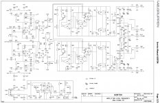
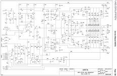
From their service schematics fP2200 they mention the use of flyback converts, a bit different topology.
Good luck with an interesting project! 🙂
It was already suggested in post #55.
Hello Dadod, I would also recommend reviewing the Swedish company Lab.Gruppen Class TD® amplifiers.
Here are some service schematics:
Free Labgruppen Diagrams, Schematics, Service Manuals :: Schematics Unlimited
And their patent USPTO #5,200,711
US Patent Full-Text Database Number Search
From their service schematics fP2200 they mention the use of flyback converts, a bit different topology.
Good luck with an interesting project! 🙂
Thanks for the links

Thanks for the links
Thank you too Harry for the courtesy.
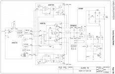
Btw, I have to correct my self regarding the previous post after having examined the schematics a bit closer, the fP2200 (incl. fP2400q, fP2600) is not a Class TD topology, but the fP3400 and fP6400 are, and they use fixed frequency PWM buck converters feeding the OP stage, if I got it right this time.
Regards
Attachments
Rather than switch the supply rails, you can correct for the shortcomings of the class D with error correction using a small, wide bandwidth class A amplifier. Since the error between the input Vi1 and the feedback voltage Vi2 is very small within the bandwidth of the system, you only need a small error correcting current through Rsum to remove any distortion.
You may argue that this is not a class A system, but I think you could make the case that if A3 is class A, the system could be classed as a class A amplifier with a class D simply providing the high power 'heft'.
Conceptually this sounds similar to the Feed-Forward error-correction system that Sansui used in the early 1980s. US patent number 4,367,442. US4367442.pdf
Attachments
How to design 200W Class A power amp with very high efficiency, that was my interest last few months. Some kind of combination of Class A and Class D or T, but what is simple way to do that.
There are different ways to do that, I don’t have all information what’s going on in commercial audio, but I haven’t seen the way I will present here. Normal Class A amp has very low efficiency of around 30%, but with this approach presented here it could be much better with similar sound benefits.
The power amp I will use is modified 100W CFA and 200/400W Class D amp. This CFA is quite similar to my Class AB amp but the output MOSFETS are biased to Class A and power supply is only +-6V with middle point not connected to the ground but to the Class D amp output. Both amps should have the same gain.
I ordered two Class D amps in kit from China and now waiting to arrive, and then I will check if this concept is viable. Simulation shows very good results regarding both, distortion and efficiency.
The Class A amp needs two separate power supply one high voltage for the input blocks and one low voltage for the output transistors.
Attached the schematic as simulated, FFT plot of the Class A amp and to compare with some distorted FFT of simulated Class D amp and the SRPP plot of the output low voltage power MOSFETs. It’s quite easy to find a Class D amp with similar or lower distortion than the one I used in simulation(not real, I used ideal voltage source with distorted input).
Damir
This was my idea! 🙂 The difference is you know how to do it and I don't😂 Please do it and do it good! I would buy one 🙂
Building a Class D amp acting like Class A. Is it possible?
Hahahaha of course I know there are hundreds who thought about it before me. Mine was just a joke. Idea is something to excute it is something🙂 I had a similar YouTube idea YEARSSS ago but the idea just stayed there🙂 Idea is just a small part of it IMO.
Conceptually this sounds similar to the Feed-Forward error-correction system that Sansui used in the early 1980s. US patent number 4,367,442. US4367442.pdf
Indeed - I think the main difference is the use of a class D amplifier to provide the power.
It will need a bit more thought - I am thinking of ways to simplify the signal summing through Rsum
Bonsai, I have the schematics for at least one of these Sansui amplifiers. Feel free to send me a PM with your email address if you would like a copy.
Design and Construction of a Feedforward Error Correction Amplifier
Takahashi, Susumu; Tanaka, Susumu
AES Convention:65 (February 1980) Paper Number:1614
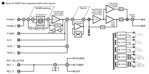
When we tried to make reverse engineering of AU-D9 we found that the low power amplifier (correction buffer) and ff network were not stuffed 😀 The amplifier sounded good though
Takahashi, Susumu; Tanaka, Susumu
AES Convention:65 (February 1980) Paper Number:1614
When we tried to make reverse engineering of AU-D9 we found that the low power amplifier (correction buffer) and ff network were not stuffed 😀 The amplifier sounded good though
Attachments

Hi Damir
Did you ever finish this?
Best wishes
David
Hi David,
Not yet. I am having cataract surgery, one eye finished one to go, so next 30 days I have to be careful with my eyes and then I will start with this project. I hope this winter it will be finished.
Best wishes
Damir
I have to be careful with my eyes...
I hope the operation is trouble free and that you are fine.
In the meantime I will think about efficient amplifiers.
Best wishes
David
...power losses for non-resistive load- like ...a speaker!
Hi Harry (if you are still here while Damir recuperates)
I think the same loses would apply to simple buck down-converters, as used by Labgruppen.
They seem to be almost the default choice for professional use so presumably it not too serious.
Have you simulated or calculated this to see how much it difference it makes?
I also noticed the so-called "BASH" amplifiers.
They use a double ended linear amp, so they can just one class-D amp.
Seems clever but I haven't studied it yet.
Have you (or any lurkers) any comments on it?
Best wishes
David
I think the same loses
Same as what?
Have you simulated or calculated this to see how much ... difference it makes?
No. I'm afraid the best I can offer is this rather vague observation: it's very tricky to determine what the real-world result will be, because it depends heavily on factors which vary wildly, namely the program material and the load. If this combination gives rise to frequent large phase disparities between output voltage and current, then the impact on losses will be very significant.
It may also cause interesting distortion effects, because when the output voltage and current have the same polarity, the conducting linear-stage output transistor will be operating under constant Vce, but if current and voltage have opposing signs, the output transistor Vce will be varying, increasing distortion.
I also noticed the so-called "BASH" amplifiers.
Do you have a link?
Last edited:
Same as what?...then the impact on losses...
I didn't write very clearly, I meant to compare the losses of a class-D solution, like Damir proposes, to a circuit that only sends the rails down to zero, same as the Yamaha EEE, the Labgruppen or the Carvers I have seen.
I realize it's very dependent on details of the input and the load.
I just wondered if you had a feel for how much difference it made it practice, with realistic speaker loads to shift the phase.
I see the benefits of Damir's approach in terms of constant Vce but perhaps a simpler approach will work as well in practice.
Do you have a link?
The product was aimed at the OEM market and information is a bit scarce, commercial-in-confidence and all, but I tracked down what seems to be the key patent. US5075634A - Composite bridge amplifier
- Google Patents
Best wishes
David
The product was aimed at the OEM market and information is a bit scarce, commercial-in-confidence and all, but I tracked down what seems to be the key patent. US5075634A - Composite bridge amplifier
- Google Patents
Excellent, thanks 🙂 Hadn't come across that one before; it's an interesting approach.
Sorry I couldn't be more helpful with the other question 🙁😱
...Hadn't come across that one before...
Here's another question for you, and Markus or others "skilled in the art".
Have you ever considered a Zero Current Switched/ZVS circuit for a class-D amp?
There's been a lot of work on this for SMPS for the usual reason of increased efficiency, but it has the nice bonus of reduced EMI, and potentially faster I suspect.
Seems like it would be a clever idea for class-D but I haven't seen it.
Have I just missed it because class-D isn't my area or is this a step forward?
Best wishes
David
The challenge there is to maintain the zcs or zvs condition for all input/output scenarios, without adversely affecting distortion. Having an auxiliary leg that injects the right amount of current into the switch node is one possible approach but is expensive to implement.
...maintain the zcs or zvs condition for all input/output scenarios...
SMPS with LLC to maintain ZVS/ZCS seem to be the current state of the art (or perhaps only flavour of the month, I just started to study this).
It does look like it can maintain ZVS over a reasonable variation.
Best wishes
David
- Home
- Amplifiers
- Solid State
- 200W Class A amp with high efficency