Can more simple since the ground needs no current.What about a power supply like this?
Mona
Attachments
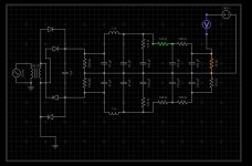
Yes, quite bad. Like almost all audio "grounded grid" circuits, no grid is grounded. It will have quite poor line driving ability, due to the low current in the output side. If the ECC83 cathode voltage is correct then it will suffer from grid current and so need driving from a low impedance source; the feedback resistors set rather a high impedance for the second ECC83 grid too. Difficult to conceive which modern system will need a voltage gain of x6 too. Almost a textbook example of how not to design a valve circuit.Ketje said:To get an idea of what this is all about i tryed to reverse engineer from the photos of the preamp the schematic.
Must say, not too happy with what i found
Last edited:
7K plate resistance of 12AU7 is for HIGH current.
It is the "show-off spec" to illustrate what the tube "can" do.
We almost never run them near that hot in small audio.
Key concept: the tube and the plate resistOR will be picked and biased for "a fair fight". The 12AU7 with 51K plate resistor will typically be biased down from 10mA to maybe 2mA or less. Or a rule of thumb: the plate Voltage will be 1/3rd to 2/3rd of the supply voltage. And the plate resistor will be the other 2/3 to 1/3 of the supply voltage. So 1.3mA to 2.6mA per 51K resistor. If you have three such resistors, 6mA to 13mA total.
An old rule-o-thumb for picking the first filter cap is 1uFd per mA. 13uFd!! Yes you "can" get 4,700uFd. But the same amount of stuff will build hundreds of smaller caps. And you get a LOT more filtering with a C-R-C-R-C-R-C-R-C chain than a C or a C-L-C-R-C chain.
The multiple added uFd do not just add, they *multiply*. Like from a 6dB/oct 1st-order filter to a 30dB/oct 5th-order filter.
BTW: 4,700uFd for 10mA load, you switch off the B+ and leave the heaters hot, it will keep playing for 3 minutes. If you turn off both B+ and heaters, the cap will hardly drain before the heaters cool, and the cap may hold 150V for days. With more rational size caps the tubes drain a fair part of the charge before the heaters cool.
7K plate resistance of 12AU7 is for HIGH current.
It is the "show-off spec" to illustrate what the tube "can" do.
We almost never run them near that hot in small audio.
Key concept: the tube and the plate resistOR will be picked and biased for "a fair fight". The 12AU7 with 51K plate resistor will typically be biased down from 10mA to maybe 2mA or less. Or a rule of thumb: the plate Voltage will be 1/3rd to 2/3rd of the supply voltage. And the plate resistor will be the other 2/3 to 1/3 of the supply voltage. So 1.3mA to 2.6mA per 51K resistor. If you have three such resistors, 6mA to 13mA total.
Very good to know!
An old rule-o-thumb for picking the first filter cap is 1uFd per mA. 13uFd!! Yes you "can" get 4,700uFd. But the same amount of stuff will build hundreds of smaller caps. And you get a LOT more filtering with a C-R-C-R-C-R-C-R-C chain than a C or a C-L-C-R-C chain.
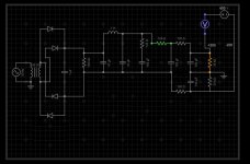
I found that even a 47uF, 1H, 47uF was effective. I can go smaller still. I learned another trick too, how to adjust your Q on a CLC filter like that. See attached picture. Every time I simulate an LC filter with that additional series RC in parallel, it has a great effect on eliminating the LC resonance!
The multiple added uFd do not just add, they *multiply*. Like from a 6dB/oct 1st-order filter to a 30dB/oct 5th-order filter.
BTW: 4,700uFd for 10mA load, you switch off the B+ and leave the heaters hot, it will keep playing for 3 minutes. If you turn off both B+ and heaters, the cap will hardly drain before the heaters cool, and the cap may hold 150V for days. With more rational size caps the tubes drain a fair part of the charge before the heaters cool.
So I approached this with two or three things in mind:
1. Bigger caps = less ripple and more stability
2. Just get flat B+ voltage to the tubes and everything will be fine
3. There's no kill like overkill.
Came out with this:
- Learned massive inrush of current is bad as a result
- Learned PSUs need to be balanced for their loads
- Learned I've completely not predicted the load properly
- Learned electricity is like water in a pool, and there are many considerations to make in high voltage power.
- Learned I need to make one of them safety light bulb things first.
- Learned circuit simulators are primitive.
- Learned how to use LTSpice!
Attachments
Can more simple since the ground needs no current.
Mona
I see, so throw a voltage divider in at the end and connect it to ground. K!
Thanks.
Primitive in what way? AFAIK, most modern circuit designs rely heavily on circuit simulators of one type or another...[*]Learned circuit simulators are primitive.
Sorry but you started with the wrong foot.
* You bought a center tapped 382V transformer meant for a 2 diode "full wave" rectifier but show it connected to a bridge rectifier, so actual VAC is 382 and rectified volotage on first cap will be scary 540V DC.
* Not sure why you chose *huge* (should I say impractical?) 4700uF as the first cap value.
Yes, it *will* work there, same way as a 200HP electrical motor will run your bench drill press. (hint: usual value is 1/4 to 3/4 HP).
It will also take such a long charging pulse (during which it looks like a short) than it might even blow the 1N4005 diodes.
* given such a huge capacitor and light load it will amount to negiglible ripple to begin with,so there is not much need for the filtering inductor ... which also won´t do much in any case, just calculate ripple values before and after it.
The following RC cell will work nearly as well, and is more reasonable, from a practical way.
* just a small point, but I guess you are building a preamplifier, not an amp.
You can rest easy there sir! I haven't bought a single thing yet. Haven't I agreed as much already, that these aren't great ideas?
Yes, this PSU is for a pre-amp. I do have some other designs for PCBs for which I will have to design other PSUs for.
Although I won't be using a large capacitor, I did experiment with a mosfet connected to a voltage divider, which toggles a relay. Now the relay was in front of the buffer cap, to switch between a high current power resistor. This would slow down the voltage draw until it passes a certain voltage, then it would charge as normal.
But again, that was too large an input cap.
When I look up that transformer with the 380CT, the spec sheet says 380 Red to Red. Yeah, that would be bad for a single rail B+ of 200v. But it'll be fine for a dual rail supply. I agree that the diodes are not up to the task. I meant those to stay under 300v.
Now with ripple, the problem I'm targeting is, I don't know how to figure out what ripple reduction to target yet.
Edit: not entirely sure on the transformer. It seems I don't need one with such a high current rating, so if I could get a small one that'd be dope.
Last edited:
Primitive in what way? AFAIK, most modern circuit designs rely heavily on circuit simulators of one type or another...
I was reading about the ups and downs of circuit simulators. How you need to define more detailed models of circuits than the ones that come in LTSpice.
Or take for instance EveryCircuit, which is more like a playground, their inductor model only has an option for setting inductance, it doesn't have parameters for parasitic capacitance or resistance.
The models can be as simple as you like or as complex as you like. Not sure which models - "the ones that come in LTSpice" - you are referring to. You have to bear in mind, LTSpice was created for SMPS designs, to use it for other types of circuits, it is up to you, the user to create accurate models, but for a simple linear PS, you should not have any issue with the "primitiveness" of SPICE.How you need to define more detailed models of circuits than the ones that come in LTSpice.
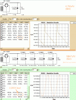
JM, I'm not sure I would call the single 4,700uFd design "negligible ripple".
Using near-ideal parts I get 35mV ripple, and a really ugly waveshape. With some assumptions, this may be 10mV ripple on first plate and 1,000mV (1V!) on the third plate.
With realistic part and wiring parasitics it will be worse. Past some point, over-kill is money down the toilet.
To add to my many-small-caps point, much less uFd can give 2,000 less ripple, for a small loss of DC voltage. (Less loss with choke.)
Attachments
Seems that, other than the choke + cap causing an oscillation, they're extremely effective at attenuating ripple.
Give JM a break, he just wanted to club me over the head.
Plus I'm going to start prototyping using a 12V C.T. transformer and some prototype PCB dev board. (Do power circuits typically linearly with voltage? Does a lower voltage circuit typically behave like a higher voltage circuit in most senses?)
Or save yourself a lot of time, money, and effort and just use one of these.
DC-DC 8-32V to 45-390V Step Up Power Supply Module High Voltage ZVS Boost Module | eBay
Power it with one of these.
AC100-240V To DC 12V/24V 2A -10A Power Supply Adapter Driver Switch For strip | eBay
You run the heaters from the 12V supply and the rest from the boost converter.
Cheers.
DC-DC 8-32V to 45-390V Step Up Power Supply Module High Voltage ZVS Boost Module | eBay
Power it with one of these.
AC100-240V To DC 12V/24V 2A -10A Power Supply Adapter Driver Switch For strip | eBay
You run the heaters from the 12V supply and the rest from the boost converter.
Cheers.
What's the ripple like on that sketchy-lookin doohickey?
I mean, all I need is under 30mA, but should I add additional filtering?
I mean, all I need is under 30mA, but should I add additional filtering?
Oh, quite the contrary 😛Give JM a break, he just wanted to club me over the head.
I wanted to save you the depressing/frustrating experience of having the caps explode (because of the unexpectedly high 540V DC being slammed into them), 1N4005 diodes cracking or catching fire because PIV would be amply exceeded, etc.
Now knowing that you spent no money on the heavy stuff but instead are researching first and to boot, experiment small scale (low voltage stuff) makes me happy

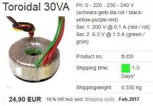
So I'm frustrated in looking for transformers. I'm looking for something 180V AC RMS, but websites like digikey and mouser have a gap between 120 and 200. And all their 200+ stock is Triad and Hammond.
180 V is ideal for one of the circuit boards, because it doesn't require a -200, just a +200 and ground. A 360v transformer is good for more powerful supplies, of which I am not making. Yeah, what if you only want to make a 10-30mA supply?
180 V is ideal for one of the circuit boards, because it doesn't require a -200, just a +200 and ground. A 360v transformer is good for more powerful supplies, of which I am not making. Yeah, what if you only want to make a 10-30mA supply?
- Status
- Not open for further replies.
- Home
- Amplifiers
- Power Supplies
- 200V Tube Amp Power Supply