In real life everything is a compromise ;-). As mentioned I do think that what you do have now appears to be already very good even though it is not 100% optimized to a true LR6 with 100% identical phases of both ways over the whole range. Things may or may not audibly improve/change significantly and only way to find out is to really implement it, preferably with a DSP-based crossover running on a PC for convenience, or one of those PA "loudspeaker management" units from dbx or other companies.Hi KSTR,
I see what you mean, but in reality the crossover in my system wasn't targeting a symmetrical 6th order LR.
Rather, the process was:
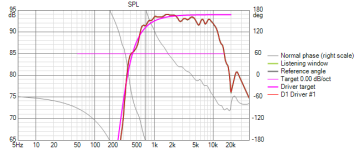
1) set LP to 6th order LR acoustic @500Hz (6th order electrical topology required to achieve this)
2) set HP to 2nd order electrical, and adjust corner frequency and "shape" so as to obtain -6dB @500Hz AND the best achievable phase match when the horn is physically positioned with some workable front-to-back offset relative to the woofer (i.e., acoustic centres not aligned).
It just so happens that, given the natural roll-off of the unfiltered driver+horn (approximating a 4th order HP @300Hz, but transitioning to an even steeper quasi-6th order at even lower frequencies)... the acoustic HP transfer function ends up resembling a 6th order LR.
There are so many variables in speaker design and usage. A proper XO is only one of them, though definitely an important foundation.
BTW, I think your 500Hz XO point might be a bit borderline, the HF driver working quite outside of its comfort zone when pushed and the horn loading already fading out?

They are VCad sims but using actual measured individual frequency responses.Hey, quick question. Any acoustic measurements? (non VCad i mean. They all appear to be sims, or am i misunderstanding them, thx.)
Complete system measurements in room are compromised by room acoustics, so less illustrative of the design per se.
I first simulate the summed response, varying the offset until the best phase match is obtained.
Then, I measure the impulse responses of the filtered woofer and driver+horn from the listening position, keeping the same fixed "time of flight", and I post-process the two impulse responses to limit the frequency "window" to the crossover freq.
The resulting "filtered" impulses should then overlap. If they don't, I measure their "distance" D (in milliseconds), and move the horn to the front or the rear accordingly.
Then, I repeat the measurements to confirm, and proceed to make further offset adjustments as needed.
Sounds complicated, but it's really rather quick and straightforward once you get the hang of it.
The actual electrical HP is approx. a 2nd order Butterworth @650Hz, and the horn is a hypex with a cutoff = 300Hz. So the driver is well protected from overexcursion - at least at domestic levels ... and that includes occasional brief 110dB peaks ;-)BTW, I think your 500Hz XO point might be a bit borderline, the HF driver working quite outside of its comfort zone when pushed and the horn loading already fading out?
Superb implementation of an acoustic LR6 crossover.
It echoes the original Ariel crossover, which was electrical 2nd-order, and acoustical 4th-order. It's not surprising a horn system requires a higher-order crossover, because horns, as a group, have higher-order cutoffs than direct-radiator tweeters.
And there's nothing wrong with that, since horns have much lower distortion ... in their passband, which is the whole point of using them. Keep out-of-passband energy out, and you get a high-dynamic-range system.
Poor Marco: having explained a few times now the design was not intended as an acoustic LR6 he keeps getting compliments for "doing a LR6 right"...Superb implementation of an acoustic LR6 crossover.
And another thing: those who have simmed and actually built filters with more than 24db/oct (36 or 48) acoustic slopes will have discovered that target matching is getting easier the steeper the slope is. LR8 is near ideal in the stopband.
LOLPoor Marco: having explained a few times now the design was not intended as an acoustic LR6 he keeps getting compliments for "doing a LR6 right"...
YES 🙂And another thing: those who have simmed and actually built filters with more than 24db/oct (36 or 48) acoustic slopes will have discovered that target matching is getting easier the steeper the slope is. LR8 is near ideal in the stopband.
As the xover slope/order gets steeper, it gets easier to have the electrical xover become the realized acoustic xover.
To the point electrical and acoustic xovers can become the exact same thing..
P.S. I found this other old post that gives detailed instructions using HolmImpulse: https://www.diyaudio.com/community/...requency-impulse-response.144984/post-4479940I first simulate the summed response, varying the offset until the best phase match is obtained.
Then, I measure the impulse responses of the filtered woofer and driver+horn from the listening position, keeping the same fixed "time of flight", and I post-process the two impulse responses to limit the frequency "window" to the crossover freq.
The resulting "filtered" impulses should then overlap. If they don't, I measure their "distance" D (in milliseconds), and move the horn to the front or the rear accordingly.
Then, I repeat the measurements to confirm, and proceed to make further offset adjustments as needed.
Sounds complicated, but it's really rather quick and straightforward once you get the hang of it.
This is essentially the same method that I use, but relying on directly matching the measured 1/3-oct smoothed phase responses, instead of the frequency-windowed impulse responses. Both approaches lead to the same result.
Yes, 'time zero locked' measurements is the only method I know/trust, for determining z-axis offsets.This is essentially the same method that I use, but relying on directly matching the measured 1/3-oct smoothed phase responses, instead of the frequency-windowed impulse responses. Both approaches lead to the same result.
Different techniques using that method, give slightly different z-axis results, but all converge closely ime.
And i meant to say thx for your previous reply about your method. I was really just curious if z-azis was solely from sims, or if measurement was involved.
Those horns are beautiful! It’s like looking at Troy’s (Joseph Crowe) horns… horn porn! I’m planning a 15”/CD build now but alas not with horns like that. My CD’s (N314X) are in but everything else is going to take months to come in so mine will end up being a springtime build.
- Home
- Loudspeakers
- Multi-Way
- 2 way "TAD-inspired" / "Beyond the Ariel-type" medium-high efficiency system