Care to share:
Graphs of raw driver responses (+ .frd or .txt file would be ideal)?
Idem filter transfer functions (+ idem)?
final acoustic responses ( + idem )?
Graphs of raw driver responses (+ .frd or .txt file would be ideal)?
Idem filter transfer functions (+ idem)?
final acoustic responses ( + idem )?
A few graphs below:
1) "raw" Woofer on axis

2) "raw" Woofer 30deg off axis

3) Low-Pass filter transfer function

4) Filtered Woofer on axis

5) "raw" driver+horn on axis (with and without passive parallel-RLC eq contour network)

6) "raw" driver+horn 30deg off axis (with and without passive parallel-RLC eq contour network)

7) High-pass filter transfer function

8) Filtered driver+horn on axis

1) "raw" Woofer on axis
2) "raw" Woofer 30deg off axis
3) Low-Pass filter transfer function
4) Filtered Woofer on axis
5) "raw" driver+horn on axis (with and without passive parallel-RLC eq contour network)
6) "raw" driver+horn 30deg off axis (with and without passive parallel-RLC eq contour network)
7) High-pass filter transfer function
8) Filtered driver+horn on axis

Thank you. How close was your mic?
Any chance you can show us a combined response showing 500 Hz, with and without phase reversal?
Btw I like the gentle slope downward you achieved on the compression driver response. I bet it sounds nice and non fatiguing. Too often the presence region is over emphasized. Thanks for sharing 🙏.
Any chance you can show us a combined response showing 500 Hz, with and without phase reversal?
Btw I like the gentle slope downward you achieved on the compression driver response. I bet it sounds nice and non fatiguing. Too often the presence region is over emphasized. Thanks for sharing 🙏.
Stunning project! I bet this speaker gives goosebumps in spades triggered by the explosive dynamics and perceived resolution.
Chiming in with my 2ct., to implement a horn setback, one then would need the woofer to be electrically delayed by the same amount with a delay allpass or delay lowpass (at >> f_c). OTOH, simply flipping polarity always is a dirty trick that IMHO doesn't really work (even with flattened summed response it will not sound very coherent).
Theoretically a proper setback would improve off-axis behavior at XO as the sound sources are closer together (notably for rear off-axis the source of the horn is the mouth rather than the throat). The woofer also would see less obstacles that diffract and bend its wave-front.
Back to the XO. IME, the magic of the Linkwitz-Riley is only brought to light when it is phase-clean so to say, no patch-working tricks. The phase of the summed response must follow the textbook LR6 allpass response which means the individual phases must not only match around the XO but must also be exactly the same with regard to total phase rotation, as much as practically feasible, of course (say, matching to about -30dB magnitude down around the XO in both directions).
In the time domain this means both ways put out almost exactly the same waveform at the same time for narrow-band tonal transients (5-cycle shaped tone bursts etc) which keeps the sum as compact as possible, no stretching/smear.
As a final thought, with that clean LR6 you could put the icing on the cake by using DSP to unwrap the allpass phase (excess phase) to make the whole thing transient perfect, increasing realism and speed even further, given that low XO point where phase contribution is likely to be more audible.
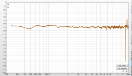
That looks definitely very good. As far as I can see, you've aimed for a straight LR6 acoustic target, and that would mean the woofer and tweeter diaphragms are roughly in the same plane and the tweeter runs inverted polarity.It works exactly as intended. I.e., the asymmetrical crossover slopes work in tandem with the unfiltered "raw" driver responses AND their relative physical offset to arrive at the desired phase match over a frequency range centred on the crossover frequency.
See phase measurements below:
View attachment 1235842
Chiming in with my 2ct., to implement a horn setback, one then would need the woofer to be electrically delayed by the same amount with a delay allpass or delay lowpass (at >> f_c). OTOH, simply flipping polarity always is a dirty trick that IMHO doesn't really work (even with flattened summed response it will not sound very coherent).
Theoretically a proper setback would improve off-axis behavior at XO as the sound sources are closer together (notably for rear off-axis the source of the horn is the mouth rather than the throat). The woofer also would see less obstacles that diffract and bend its wave-front.
Back to the XO. IME, the magic of the Linkwitz-Riley is only brought to light when it is phase-clean so to say, no patch-working tricks. The phase of the summed response must follow the textbook LR6 allpass response which means the individual phases must not only match around the XO but must also be exactly the same with regard to total phase rotation, as much as practically feasible, of course (say, matching to about -30dB magnitude down around the XO in both directions).
In the time domain this means both ways put out almost exactly the same waveform at the same time for narrow-band tonal transients (5-cycle shaped tone bursts etc) which keeps the sum as compact as possible, no stretching/smear.
As a final thought, with that clean LR6 you could put the icing on the cake by using DSP to unwrap the allpass phase (excess phase) to make the whole thing transient perfect, increasing realism and speed even further, given that low XO point where phase contribution is likely to be more audible.
They sound just fine to me. Very natural and transparent, not drawing attention to themselves, but fresh and "airy" when called for.How are the highs? It looks like it rolls off at around 12khz.
I had a supertweeter in the previous iteration of my system (different horns and crossover)... and I don't miss it now.
A friend of mine had the JBL 2450 (2" exit version), retrofitted with a Truextent Beryllium diaphragm. They sounded great on the top end but we never measured them.
How do you feel about 1.4" (or JBL 1.5") Exit CD/horns?They sound just fine to me. Very natural and transparent, not drawing attention to themselves, but fresh and "airy" when called for.
I had a supertweeter in the previous iteration of my system (different horns and crossover)... and I don't miss it now.
The topology of my speaker (15 in + CD on horn) and filter are not that different than yours, Marco, except I cross over higher (700 HZ).
Well, I actually use REW -> All SPL -> Control -> Alignment Tool, which is convenient and more precise for doing the same thing.
In any case, being in luck, the horn mouth lands very close to the plane of the woofer baffle, minimizing diffraction, improving off axis listening, and reducing speaker depth.
The attenuation of the CD can be slightly reduced to compensate for the increase in distance. Crossing at 500 HZ will yield another position.
Attached is the unfiltered group delay measured 24 in (60 cm) in front of my speaker. Doesn't look too bad?!
I am not showing the imperfect step response (woofer leading edge starting ahead of CD spike). Yet the speaker sounds quite nice IMO. And how many real speakers have a nice step response? I confess that my left brain warns "not optimal." However my right brain is in bliss.
Looking for views on this, or another filter topology that works better in practice (factoring drivers roll off and such) for two ways like ours.
PS: KSTR, I am intrigued by your post. You do realize that our crossovers are not symmetrical? (woofer is delayed through a higher order filter). Can you elaborate on what we can do better?
- 6th order on woofer + resistor in parallel with first coil for baffle step compensation.
- RC contour followed by 2nd order high pass on the compression driver.
Well, I actually use REW -> All SPL -> Control -> Alignment Tool, which is convenient and more precise for doing the same thing.
In any case, being in luck, the horn mouth lands very close to the plane of the woofer baffle, minimizing diffraction, improving off axis listening, and reducing speaker depth.
The attenuation of the CD can be slightly reduced to compensate for the increase in distance. Crossing at 500 HZ will yield another position.
Attached is the unfiltered group delay measured 24 in (60 cm) in front of my speaker. Doesn't look too bad?!
I am not showing the imperfect step response (woofer leading edge starting ahead of CD spike). Yet the speaker sounds quite nice IMO. And how many real speakers have a nice step response? I confess that my left brain warns "not optimal." However my right brain is in bliss.
Looking for views on this, or another filter topology that works better in practice (factoring drivers roll off and such) for two ways like ours.
PS: KSTR, I am intrigued by your post. You do realize that our crossovers are not symmetrical? (woofer is delayed through a higher order filter). Can you elaborate on what we can do better?
Attachments
Assuming that you are not actually listening to the system from 60cm away, the real group delay from your listening position will be different (trigonometry!)Attached is the unfiltered group delay measured 24 in (60 cm) in front of my speaker
The best way to estimate GD at listening position is to model/simulate it in software, calculating the summed response (woofer + driver), setting the driver offset set = real offset at listening position, determined by impulse measurements.
I cannot see an asymmetric crossover in Marco's measurements (flipped the woofer plot and overlaid it with tweeter plot). Looks like textbook LR6 to me:PS: KSTR, I am intrigued by your post. You do realize that our crossovers are not symmetrical? (woofer is delayed through a higher order filter). Can you elaborate on what we can do better?
Maybe you mean the electrical filter responses? But those are completely irrelevant, they are just dialed in to whatever is required to arrive at the acoustic target and have no value in itself. BTW, in my whole life I never got one of the textbook electrical filter functions with one single and obvious exception, that is two identical fullrange drivers used as woofers and tweeter to audibly study crossovers.
The Linkwitz-Riley XO is established only when there is no offset of acoustic centers, diaphragms need to be in the same plane. Polarity of the ways is governed by total filter order, orders 2, 6, 10, ... have to invert one way, orders 4, 8, 12,... have same polarity on the drivers.
If is very important to understand that phase is more important than amplitude. In the given case, the final woofer low-frequency roll-off will slightly skew the phase of the woofer at 500Hz and to keep the LR characteristic the tweeter must have the exact same phase response. The end result is that the final acoustical target functions are not pure/isolated Linkwitz-Riley anymore. This is even more obvious with a 3-way speaker. For an LR alignment for both XO points, the final target functions for woofer and midrange drivers will completely be different from the pure/isolated LR functions.
If we want to introduce an offset of acoustic centers, the only way to do that is to electrically compensate the path delay with the shorter time-of-flight to match the other way, in order to establish the "diaphragms in the same plane" requirement. Delaying a woofer is easy with simple analog means, delaying a tweeter almost impossible, therefore tweeter setback is the only feasible constellation whereas woofer setback can realistically only be achieved with digital delay of the tweeter.
As for the process of deriving the required electrical filter functions, there is a strategic procedure:
- set up acoustic target functions (see notes above), using educated guesses what's going to work
- dial in coarse EQ (and setback/delay) to come somewhat close to those acoustic target function for each driver, again using educated guesses
- then fine-tune parameters until you get the best phase match throughout the XO region, ignore the non-flat summed response
- make summed response flat with global EQ
- the product of this global EQ and the individual driver filter functions give the desired electrical target functions
- approximate those electrical target functions with your actual crossover circuits or building blocks
Hi KSTR,
I see what you mean, but in reality the crossover in my system wasn't targeting a symmetrical 6th order LR.
Rather, the process was:
1) set LP to 6th order LR acoustic @500Hz (6th order electrical topology required to achieve this)
2) set HP to 2nd order electrical, and adjust corner frequency and "shape" so as to obtain -6dB @500Hz AND the best achievable phase match when the horn is physically positioned with some workable front-to-back offset relative to the woofer (i.e., acoustic centres not aligned).
It just so happens that, given the natural roll-off of the unfiltered driver+horn (approximating a 4th order HP @300Hz, but transitioning to an even steeper quasi-6th order at even lower frequencies)... the acoustic HP transfer function ends up resembling a 6th order LR.
Sure, and agreed.The final acoustic transfer function is all that matters...
My point is, though, that the final acoustic HP transfer function isn't exactly LR6.
It may superficially look like it, but it differs in terms of phase response. Hence why it works as well as it does when connected with +/+ polarity and with that particular physical offset between the two acoustic centres (which, incidentally is not exactly half wavelength at 500Hz, either).
Measuring close (here 60 cm) with windowing to reject reflections, allows setting the window duration long enough to observe what happens around a low crossover frequency like we are using. Granted, the GD difference between woofer and tweeter is sensitive to mic height, but this quick measurement shows anomalies (speaking of experience!)Assuming that you are not actually listening to the system from 60cm away, the real group delay from your listening position will be different (trigonometry!)
Simulations work too. Not disputing this!
My memory played tricks on me, and Marco's and my filter are not similar after all.
Being back home and going through my notes, here's my filter topology.
LPF
Electrical fourth order (I started with TAD's sixth and shifted to fourth around 2017).
Measured driver acoustical 9 dB/ octave roll off just above my crossover fc.
Measured roll off combined EL + Acoustical = 33 dB / octave (in between 6th and 7th order)
Retards phase approx. 5.5 x 45 degrees = 247 degrees
HPF
Electrical second order.
No apparent driver roll off immediately below crossover fc (700 Hz)
Measured driver acoustic 12 dB / octave roll off below 500 Hz, and steeper still below 400 Hz
Measured roll off combined EL + Acoustical at fc = 12 dB / octave (2nd order)
Advances phase approx. 2 x 45 degrees = 90 degrees
The phase difference around fc adds up to 337 degrees.
This being close to 360 degrees, the drivers can be connected in phase if the diaphragms are in the same plane (distance to listener).
My crossover frequency is 700 Hertz, so half a wavelength is 10 in (0.25 m). I set the horn and compression driver back by this much, and reverse the phase between drivers.
Main point is, I wanted to correct my earlier post, and clarify that there is a 2 order, 90 degrees, electrical phase difference between Marco's and my crossover.
Thank you. Although I manage by cycling through the steps in a back and forth manner, I like how your procedure sheds light on how to do things more systematically.As for the process of deriving the required electrical filter functions, there is a strategic procedure:
- set up acoustic target functions (see notes above), using educated guesses what's going to work
- dial in coarse EQ (and setback/delay) to come somewhat close to those acoustic target function for each driver, again using educated guesses
- then fine-tune parameters until you get the best phase match throughout the XO region, ignore the non-flat summed response
- make summed response flat with global EQ
- the product of this global EQ and the individual driver filter functions give the desired electrical target functions
- approximate those electrical target functions with your actual crossover circuits or building blocks
That does not sound possible to me. Way too shallow.Measured roll off combined EL + Acoustical at fc = 12 dB / octave (2nd order)
I would bet it's a measurement artifact.
Also, calculating degrees of phase shift at crossover freq. (Fx) like that doesn't really work well at all. One has to consider the actual phase response vs. frequency for both drivers, and try and get the two traces to match over as wide a frequency range (centred on Fx) as possible.
I totally get that measurements and the phase curve is the way to do it, and is the way I have done it using REW when I designed the filter. My post is a simplified sanity check.
Replace fc by Fx for clarity. I measure -12 dB / octave between 500 and 700 Hz on my HPF + CD + Horn. (Driver on horn without filter measures flat around 700 Hz). Of course there is a steeper roll off below 500 Hz due to driver and horn cut off.
Replace fc by Fx for clarity. I measure -12 dB / octave between 500 and 700 Hz on my HPF + CD + Horn. (Driver on horn without filter measures flat around 700 Hz). Of course there is a steeper roll off below 500 Hz due to driver and horn cut off.
...and that steeper roll-off below 500Hz will start "bending" the phase response well above 500Hz, meaning that the actual phase rotation will be much greater than your assumption of 90° at Fx=700Hz.Of course there is a steeper roll off below 500 Hz due to driver and horn cut off.
- Home
- Loudspeakers
- Multi-Way
- 2 way "TAD-inspired" / "Beyond the Ariel-type" medium-high efficiency system