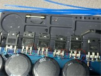
Fets are cold in normal power idle, fets get very slightly warm in half protect idle
DP1-4 read 0.33v at normal idle, DP4 and DP2 read 1.3v at half protect idle, DP3 and DP1 read 1.13v at half protect idle
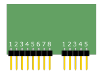
Which pins are 10 and 11? (Which side is 1 so I know for future reference)
DP1-4 read 0.33v at normal idle, DP4 and DP2 read 1.3v at half protect idle, DP3 and DP1 read 1.13v at half protect idle
Which pins are 10 and 11? (Which side is 1 so I know for future reference)
Attachments
What's the rail voltage difference at normal idle vs 1/2 protect?
Post the voltage on pins 10 and 11 in normal idle and 1/2 protect.
For most of these boards, pins are counted left to right on the side where you can see the curved part of the header pin that solders into the board. It's +F and -F.
Post the voltage on pins 10 and 11 in normal idle and 1/2 protect.
For most of these boards, pins are counted left to right on the side where you can see the curved part of the header pin that solders into the board. It's +F and -F.
Attachments
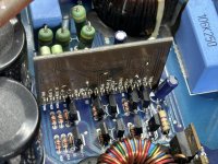
DP1-4 (voltage regulators) read 0.33v at normal idle
DP4 and DP2 read 1.3v at half protect idle
DP3 and DP1 read 1.13v at half protect idle
F+ reads 2.46v at normal idle
F- reads 2.46v at normal idle
F+ reads 2.45v at half protect idle
F- reads 2.47v at half protect idle
When reading F+ and F- the buzzing near the transformers would stop (normal idle)
Buzzing continues when meter is removed
Rail voltage normal idle vs half idle?
Connecting a 0.1uf capacitor across +F and -F may stop the buzzing.
Connecting a 0.1uf capacitor across +F and -F may stop the buzzing.
It's typically easiest on the output terminals of the rectifiers. You can measure between the output terminals of one positive rectifier and one negative rectifier or from the output terminals to ground.
That's odd. Confirm that the -F and +F are still changing normal/protect but the rail voltage is remaining exactly the same.
Those feedback terminals (±F) are taken from the rail voltage.
Those feedback terminals (±F) are taken from the rail voltage.
Half protect
119.3v positive rail
-118.4 negative rail
2.45 F+
2.47 F-
Normal idle
119v positive rail
-118.8 negative rail
2.47 F+
2.46 F-
Re-read just now
119.3v positive rail
-118.4 negative rail
2.45 F+
2.47 F-
Normal idle
119v positive rail
-118.8 negative rail
2.47 F+
2.46 F-
Re-read just now
Power idle
118.9v positive rail
-119v negative rail
2.47v F+
2.45v F-
No voltage between speaker terminal negative and primary ground
Half protect
118.7v pos rail
119.1v neg rail
2.45v both F+ and F-
0.01v between primary ground and speaker negative
118.9v positive rail
-119v negative rail
2.47v F+
2.45v F-
No voltage between speaker terminal negative and primary ground
Half protect
118.7v pos rail
119.1v neg rail
2.45v both F+ and F-
0.01v between primary ground and speaker negative
- Home
- General Interest
- Car Audio
- 2 Monoblock Class Ds Not Working, I'm Lost