In the first scenario there is ideally only a cap and perhaps a resistor on the tweeter. The impedance increase due to temp increase is what it is.
do a series XO and the XO will adjust as the temp goes up.
dave
hmm... might have missed that. So parallel suffer from impedance mismatch while series does not or less... interesting, I need to investigate that.do a series XO and the XO will adjust as the temp goes up.
dave
It can be lowpass, too. Series R, shunt C. Corner freq is still 1/(2pi*Rp*C), but the Rp in that case is the parallel combination of the series R and the amp's input resistance. Attenuation will occur, so makes sure there's enough spare gain in the system.
Never trust a claim of "first order crossover" unless they provide a plot of measured speaker output phase, step response, or group delay. Most speakers that use only a cap and woofer inductor aren't 1st order.
Never trust a claim of "first order crossover" unless they provide a plot of measured speaker output phase, step response, or group delay. Most speakers that use only a cap and woofer inductor aren't 1st order.
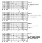
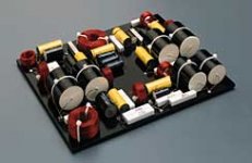
Thiel Inc. designs are technically based upon 1st order acoustic crossovers, supported by physically time aligned speakers on slanted baffles. "Back in the day" a 1st order crossover was a single capacitor or inductor, a philosophy of simplicity=perfection. An accurate 1st order acoustic Xover designed for flat SPL normally requires dozens of components(fig 1&2 from Thiel).
Attachments
Yeah, you end up with multiple correction networks. It is what it is and you work on things until it measure like you want and it plays as you want. The same thing can be said about all orders for that matter.
An accurate 1st order acoustic Xover designed for flat SPL normally requires dozens of components(fig 1&2 from Thiel).
I realise that a 1st order acoustic XO is much more complicated than a single series reactve component.
However, given the large number of components on that Thiel board, I could end up being flat broke after achieving a flat SPL in my restoration project!

… a 1st order acoustic XO is much more complicated than a single series reactve component…
Typically it is. Tysen V2’s passive 1st order XO has 3 C, 3 L, & 2 R in it (the design is proprietary so no XO map will be posted).
dave
So, is this discussion only about 1st order electrical crossovers using passive components?
I take a thread like this to mean "6dB/octave acoustic slopes" and no restriction about how you achieve such.
Like you say a 6dB/octave electrical filter has an uncertain acoustic response... so it's not really worth talking about.
Never trust a claim of "first order crossover" unless they provide a plot of measured speaker output phase, step response, or group delay. Most speakers that use only a cap and woofer inductor aren't 1st order.
:thumbup:
Is it the consensus that true 1st orders are rare and difficult to obtain due to the need for added correction networks ?
Not only that, but they fail to control diaphragm excursion. The usable lower frequency limit of all drivers is determined by the maximum amount of linear excursion. Each halving of frequency requires 4 times the excursion to achieve the same SPL. A 1st order slope only halves the excursion for each halving of frequency, therefore the diaphragm excursion will still rise out of control with reducing frequency. The only way it can work in practice is if the slope steepens from 1st order into something else and because a 1st order slope is so shallow, this will have to occur several octaves below the crossover frequency to avoid notable cancellation with the LF driver (due to phase no longer tracking). Therefore to cross two drivers 1st order, there needs to be perhaps 5 or 6 full octaves where both drivers have near-flat amplitude and phase response, and the HF driver doesn't run into a distortion issue due to over-excursion. That is a rare scenario.
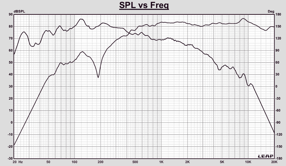
edit: Here's excursion for 1st (Red), 2nd (Green) and 4th (Cyan) order highpass filters, all Butterworth @ 1kHz.

Note that even 2nd order must steepen at some point to avoid introducing distortion due to all the out-of-band frequencies. 2nd order can steepen much closer to the crossover frequency without being noticeable: just two octaves away it is -24dB which will cause a negligible ripple in the system response if it becomes out of phase. 1st order is only -12dB at 2 octaves away, so any deviation in the phase will cause noticeable ripple.
edit: Here's excursion for 1st (Red), 2nd (Green) and 4th (Cyan) order highpass filters, all Butterworth @ 1kHz.
Note that even 2nd order must steepen at some point to avoid introducing distortion due to all the out-of-band frequencies. 2nd order can steepen much closer to the crossover frequency without being noticeable: just two octaves away it is -24dB which will cause a negligible ripple in the system response if it becomes out of phase. 1st order is only -12dB at 2 octaves away, so any deviation in the phase will cause noticeable ripple.
Last edited:
Each halving of frequency requires 4 times the excursion to achieve the same SPL. A 1st order slope only halves the excursion for each halving of frequency, therefore the diaphragm excursion will still rise out of control with reducing frequency.
I found this explanation to be very useful - thanks!
It is less extreme than described by TMM. Keep in mind that the excursion of the raw driver does not rise eternally because it follows a lowpass function and not that of an integrator of 2nd or higher order.
Edit: The cyan curve Looks a Little like the typical excursion curve of a tweeter with first order crossover.
Regards
Charles
Edit: The cyan curve Looks a Little like the typical excursion curve of a tweeter with first order crossover.
Regards
Charles
Last edited:
I think TMM explained that very well. And got it right.
Lynn Olson said much the same thing:
Quite a compelling argument against 6dB filters. It's no different from the way power handling rapidly worsens at low frequencies with woofers. Even 12dB slopes don't work well without some inherent tweeter mechanical rolloff which takes them near 18dB/octave slopes.
I suppose the motivation is that thing called "Linear Phase" or good impulse or step response. Fool's Gold, IMO. Simply the arrow of time. I am very happy with LR4 or fourth order slopes. If there is a ringing nature to them, it doesn't intrude for me. John Kreskovsky and Steen Duelund probably take this whole filter theory maths as far as it can go. And it IS maths.
With higher order, distortion is better. Now distortion DOES intrude for me. I don't like it.
There are a few linear phase circuits useable at higher order, but they make near impossible demands on the midrange. These sorts of things can only work with fullrange drivers. Which is what planet10 is up to.
Lynn Olson said much the same thing:
A common but unsuspected cause of sibilance is crossing the tweeter too low, or using a shallow-slope crossover. Many designers - unfortunately, a lot of them in the high-end biz - forget that direct-radiator drivers increase excursion at a rate of 12 dB/octave. Thus, it takes a 12 dB/octave highpass filter to merely keep excursion constant in the frequency range between nominal crossover and the Fs of the tweeter.
For example, if the tweeter has a typical Fs of 700 Hz, and the intended crossover is 2.8 kHz (again, typical), it takes a 12 dB/oct electroacoustical filter to merely keep excursion constant in the very critical 700 Hz ~ 2.8 kHz range. Part of the reason that this range is so critical is that audibility of distortion is at a maximum in the 1~5 kHz region. (Perception of distortion similar to, but not quite the same as, the Fletcher-Munson curve.)
Staying with the same example, if the electroacoustical filter is 1st-order (6 dB/octave), then excursion actually increases from 2.8 kHz on down, until 700 Hz is reached. Below 700 Hz, the excursion finally starts to decrease, but not very fast, only 6 dB/octave. This is troublesome because the maximum spectral energy of many recordings is around 300~500 Hz, so energy from this range can crossmodulate with the tweeter output.
This is why auditioning with little-girl-with-a-guitar program material and a full choral piece sound different. The LGWAG is spectrally sparse, and there isn't as much chance the tweeter will be struggling with IM distortion. Throw a dense, high-powered spectrum at the loudspeaker, though, and the tweeter will start to scream - and it is very audible on massed chorus as complete breakup.
At any rate, regardless of distortion of a particular tweeter (none of them are free of IM distortion), crossovers matter. Many designers want to take the tweeter as low as possible because the polar pattern is prettier and certainly measures nicer, but the inevitable price to be paid is more IM distortion resulting from increased excursion (the linear region is most tweeters is less than 1mm). Choosing a crossover is a difficult tradeoff between narrowing of the vertical polar pattern, IM distortion from out-of-band excursion, and how close the designer wants to approach the region of midbass driver breakup. The tradeoff is made more difficult when a rigid-cone (Kevlar, metal, ceramic, etc.) midbass driver is chosen, because the onset of breakup commonly falls in the 3~5 kHz region, right where the ear is most sensitive to distortion.
As you can see, the worst possible solution is a 1st-order crossover combined with a midbass driver that has a severe breakup region (Kevlar drivers, I'm looking at you). The 1st-order crossover fails to control out-of-band excursion, so program material in the 700 Hz-2.8 kHz region results in IM distortion in the tweeter's working range, while plenty of midbass breakup in the 3~5 kHz range gets through as well. And midbass breakup sounds the same as a bad tweeter, since the distortion and resonances fall in the same frequency range.
As a side note, most transistor amplifiers (including very expensive high-end products) go from Class A operation to Class AB around 1 watt. Feedback helps, but cannot fully overcome the two-to-one shift in transconductace as the AB region is traversed. In addition, thermal tracking is typically several seconds to a minute late (depending on the thermal mass of the heatsink and location of bias sensor), so the correct AB bias point is actually several seconds behind the program material. There are various sliding bias-tricks available (which avoid complete turnoff and associated switching transition), but they are all several seconds late. The more output transistors, the more AB transitions there are, since it is impossible to have transistors exactly match the switching transition - in production, they are matched for beta (current gain), but not usually for other parameters. Change the die temperature a bit, and the careful hand-matching goes away.
To recap, if you want lots of sibilance, use a midbass driver with severe breakup in the 3~5 kHz region (this is usually obvious from unsmoothed FR curves), pick a tweeter with limited excursion capability (not always spec'ed), select a 1st-order crossover at a low crossover frequency, and use an amplifier with a very large heatsink, many transistors, and somewhat unstable Class AB biasing (thermal overshoot). That should do the trick. Plenty of distortion from many different sources, even though the overall FR curves may look harmless.
Quite a compelling argument against 6dB filters. It's no different from the way power handling rapidly worsens at low frequencies with woofers. Even 12dB slopes don't work well without some inherent tweeter mechanical rolloff which takes them near 18dB/octave slopes.
I suppose the motivation is that thing called "Linear Phase" or good impulse or step response. Fool's Gold, IMO. Simply the arrow of time. I am very happy with LR4 or fourth order slopes. If there is a ringing nature to them, it doesn't intrude for me. John Kreskovsky and Steen Duelund probably take this whole filter theory maths as far as it can go. And it IS maths.
With higher order, distortion is better. Now distortion DOES intrude for me. I don't like it.
There are a few linear phase circuits useable at higher order, but they make near impossible demands on the midrange. These sorts of things can only work with fullrange drivers. Which is what planet10 is up to.
Quite a compelling argument against 6dB filters.
I am now persuaded to experiment further with the high pass filter in my renovation project (if only to re-introduce the original 5,000Hz; 12dB/octave filter!).
Do not rule out first-order high pass filter yet, in a 3-way system there is one clever trick if the midrange is crossed over 800 Hz or higher. The filter consist of a small capacitor for tweeter, and one bigger mutual capacitor for the midrange and the system capacitor+tweeter. Slope below midrange crossover point is still 6 dB/octave for the midrange, but 12 dB/octave for the tweeter!
I’ve had excellent success using soft knee higher orders. You get the benefits of first order: broad overlap which helps horizontal off axis; lower system group delay distortion (any individual drivers contribution to system group delay lessens the lower its contribution to the system response);
With the power handling and some of the driver alignment (lobing) benefits of higher order. Win-win
With the power handling and some of the driver alignment (lobing) benefits of higher order. Win-win
Or you could use an FIR filter on a higher order design to straighten out the group delay.
If 1st order has any value it’s in the broad overlap helping horizontal directivity. The difference in GD between a 1st order and 2nd or 3 rd of reasonable response is inaudible, based on an exhaustive study of the literature of GD including core studies in audition outside “audio”
- Status
- Not open for further replies.
- Home
- Loudspeakers
- Multi-Way
- 1st order and drivers.