phase_accurate said:Just an additional remark:
As soon as your circuit is working you might find it a little noisy: In this case think about using smaller resistors like 10 k and use larger caps instead.
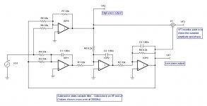
This is a subtractive-type crossover
Charles, the subtractive one would be mine -- i know about the hump, for my ap it won't be a big deal.... the tip on the smaller Rs and larger Cs is very useful as i find my parts bin low on big Rs and small Cs...
dave
SimontY said:Next step - I joined pins 6 and 7 together (B-IN >> B OUTPUT), as per richie00boy's advice, and pin 5 (B+IN) I connected to ground. This took me back to having the full AC voltage on the output.
I would just like to clarify that the 'B' op-amp is the unused one, and that your filter is built around 'A'? If so then I see no problem so far.
SimontY said:I have carefully checked my connections and to my untrained eye everything looks fine. I checked for continuity in many places and found no shorts. Power - and + go to the correct pins. Where the signal goes in appears to go through the two resistors, and the caps appear to be in the correct positions.
One thing I wonder about - where the schematic shows the output being directly connected to -INPUT --is this really just a plain short?? That is how I have connected it.
If there are no obvious mistakes remaining I think I will just pack it in and buy the correct (single) op-amp. Not like it's costing me very much money.
All that sounds fine as well. As I mentioned in an earlier post connecting the output directly to the inverting input feeds back 100% of the signal thus meaning we get unity (1x) gain.
I hope you used an IC socket 🙂 You could just drop in a TL072 if you have. Maybe the op-amp you have is not unity gain stable. If you are doing a rebuild then it would be simpler to use a single op-amp. You can get one stage working then simply cascade another identical stage to get a 24dB/oct filter.
If you are really stuck I may (if I can find them) be able to dig out an old prototype PCB (or two) of mine, I'd be willing to donate in the name of SimontY audio research 😀
"I would just like to clarify that the 'B' op-amp is the unused one, and that your filter is built around 'A'?"
Yep.
"I hope you used an IC socket 🙂"
Nope.
"You can get one stage working then simply cascade another identical stage to get a 24dB/oct filter."
I'm only looking for 12db/oct, which I will connect to my plate amp, whose 12db/oct filter will be in action, and of course variable, giving me 24db/oct or 12db + 12db at antoher fr. Some versatility, which I hope will help combat the 'wodge' of apparent output in the x-over area.
"If you are really stuck I may (if I can find them) be able to dig out an old prototype PCB (or two) of mine, I'd be willing to donate in the name of SimontY audio research 😀"
You're very kind! Let me try again first though. I feel I should be able to crack this little nut!! 😕
edit: I'll go and take a couple of photos, for amusement.

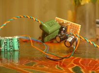

On the first pic of the PSU, I assume that bank of 3 caps on the right is two caps deep, i.e. a total of six -- 3 per rail? I assume that you have wired the PSU up like this:
What are the two black electrolytic caps on the stripboard? Chip power decoupling?
An externally hosted image should be here but it was not working when we last tested it.
What are the two black electrolytic caps on the stripboard? Chip power decoupling?
Absolutely correct Rich. I am confident in the PSU, because I very recently knocked up a p-p LM3886 tester the same way, which btw sounds pleasant. (also, the caps don't explode - surely a good sign 🙂
The black 'lytics are indeed for decoupling/bypassing (the same thing?)
Do you think it's possible everything is wired correctly, but I've fried or otherwise damaged my op-amp? I did afterall remove it from my cd player, and perhaps with heavy hands
The black 'lytics are indeed for decoupling/bypassing (the same thing?)
Do you think it's possible everything is wired correctly, but I've fried or otherwise damaged my op-amp? I did afterall remove it from my cd player, and perhaps with heavy hands
I am beginning to think that the op-amp was either damaged by desoldering or static, or is not unity gain stable. Get a DIL socket and new chip and see. If it works OK, you can reuse the chip 🙂
Bardwell's used to sell some nice red chip sockets made by Cambion. If you can't get those anymore see if they do any other 'turned pin' ones. These kind are much better than the 'wiper' type as it's easier to get the chip in.
Bardwell's used to sell some nice red chip sockets made by Cambion. If you can't get those anymore see if they do any other 'turned pin' ones. These kind are much better than the 'wiper' type as it's easier to get the chip in.
Charles, the subtractive one would be mine -- i know about the hump, for my ap it won't be a big deal.... the tip on the smaller Rs and larger Cs is very useful as i find my parts bin low on big Rs and small Cs...
Hi Dave
I did indeed make a mixup
Are you content with its outcome ? Are you interested in a symmetrical 2nd/2nd order version ?
Regards
Charles
...or maybe melted it internally during soldering?
Why not use a socket for the op-amp next time?
Jennice
Why not use a socket for the op-amp next time?
Jennice
The subtractive high/low pass network in the National Semiconductor app-note (with a second-order roll-off on both the LP and HP outputs) works very well. I use the circuit myself on a 2-way speaker. The HP and LP outputs sum flat in amplitude and phase. (But don't forget that the drivers' own response will affect this).
If you can't find the app-note I'll put the schematic on here.
If you can't find the app-note I'll put the schematic on here.
I once found this app-note accidentally.
In one of John Watkinson's books however I found a statement that subtractive crossovers could be made with almost any desired orders, symmetrial and asymmetrical.
So I did some maths and came to a simpler solution than the NS one.
Good that you like the transient perfect crossover. 😎
Regards
Charles
Jennice, I am enjoying your PDF document now. Very well presented and useful information; thank you for making it available. 😎
phase_accurate said:Are you content with its outcome ? Are you interested in a symmetrical 2nd/2nd order version ?
I've the parts piled up ready to be stuffed into the breadboard...
For the ap this version is going into i'll need 2nd/1st or maybe 3rd/1st, but i find subtractive XOs facinating so i would be interested in your 2/2. I have been following all the work you have been doing (don't necessarily grok it all).
dave
Thanks for the feed-back. 🙂
Few people ever told me what they thought of it even though it has been downloaded several hundred times. Hmmm... Maybe I just expect too much? At least the download counter tells me that it was not a complete waste of time making it.
Jennice
Few people ever told me what they thought of it even though it has been downloaded several hundred times. Hmmm... Maybe I just expect too much?
At least the download counter tells me that it was not a complete waste of time making it.Jennice
I'd like to see the app note. I think we are in very real danger of hijacking SimontY's thread though. Let us know the app note number and if needs be we can start a new thread for it.
richie00boy said:Let us know the app note number and if needs be we can start a new thread for it.
Yes please... a search turned up 34 ap notes... after the 4th one i decided i'd better ask 🙂
dave
Discussion of active crossovers is interesting to me, and relevant to the thread topic, just about.richie00boy said:I'd like to see the app note. I think we are in very real danger of hijacking SimontY's thread though. Let us know the app note number and if needs be we can start a new thread for it.
Funnily enough, I called off the search tooplanet10 said:
Yes please... a search turned up 34 ap notes... after the 4th one i decided i'd better ask 🙂
dave

- Status
- Not open for further replies.
- Home
- Design & Build
- Software Tools
- 1st attempt of 2nd order active lowpass filter failed, please advise