Well, I finished replacing the parts, put it all back together, and does it work? Nope, it powers up but there is nothing to be heard on headphones other than a fairly loud hum.
Given that I don't have a schematic to guide me, I think I'll just give up on this one as I have no idea where to start trying to diagnose the problem.
Given that I don't have a schematic to guide me, I think I'll just give up on this one as I have no idea where to start trying to diagnose the problem.
Start by reverse engineering your power amplifier. This can be a modified Dinsdale amplifier with 6 direct coupled silicon transistors or a modified Lin amplifier (5 + 1 separately).
Start by inspecting the correctness of the connections, the absence of short circuits, and circuit violations.
Check the supply voltage relative to the chassis and at test points (midpoint of the output transistors).
Or so: on the collector of the lower 1/2, and the upper one - the full supply voltage.
Last edited:
I don't have a clue how to identify test points, I have a DMM, just don't know where to even start with diagnosing.
Learn 🙂 Measure DC 200v relative to the case in one and the other channel.
At the terminals of the transistors. The voltage card is called.
At the terminals of the transistors. The voltage card is called.
Hello just tacking on to this old thread as there seems to be little information around on these amps.
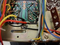
I have an FA-400 that I bought as non-working. The seller said that it had worked fine for years and then just stopped.
On the DBT it ran briefly with lots of distortion and then blew the internal fuse.
Visual issues were:
I am very new this and would be grateful for any views particularly on the mods that appear to have been made.
I have an FA-400 that I bought as non-working. The seller said that it had worked fine for years and then just stopped.
On the DBT it ran briefly with lots of distortion and then blew the internal fuse.
Visual issues were:
- Mains plug wired with exposed cores and a 13A fuse.
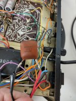
- Burned resistor on the left side of the amp board.
- Scorch marks on the inside of the casing by the accessory power outlet.
- Both left channel Toshiba 2SD234 output transistors failed. I have ordered KSD526Y as replacements.
- 1 of the 4 left channel driver transistors failed. CDC 90002 and I have ordered KSC2690 as a replacement.
- Transformer gives 39V on the amp secondary and 7.5V on the pilot light one when disconnected from the rectifier.
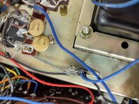
- I have an additional capacitor across the accessory power outlet that appears to be a later addition.
- There are a few rough and ready additional earth connections that do not appear on the Facebook pictures.
I am very new this and would be grateful for any views particularly on the mods that appear to have been made.
Attachments
I have found two original full size Dinsdale 10 Watt Power amplifier pcbs. Unpopulated and undrilled glass fibre boards in mint condition . They have no silk screen annotation but the Wireless World article from Feb 65 has most of the information needed to construct the amp.I think this is pretty much the same:
JLH - Dinsdale Amplifier
"R Tobey & J Dinsdale published an article "Transistor Audio Power Amplifier" in Wireless World in Nov 1961. This was modified by them in Jan 65. A Retrospect was published by them in WW in Nov 69. The first one is available in Self's site:
The Wireless World Archive
This circuit was adopted to Silicon Planar Transistors by John Lawrence Linsley Hood (JLH) and published in WW in Feb 70. At that time, I made notes and drew the circuit in my note book. I am reproducing below the circuit as well as my notes. I do not remember whether it is a regular article, circuit idea or in Letters to the Editor.
---Modified Dinsdale amplifier for use with Silicon Planar Transistors. Output 10W, 15 ohms or 15W 8 ohms. Suitable for use with either +ve or -ve ht line depending on Transistor type. Amended component values are underlined. Capacitor C5, Diode D1, and Resistors R5, R9, R10 & R12 in the original design are omitted.
The distortion is typically 0.07% at 1 KHz and 10W and the square wave response is free from overshoot or ringing even with capacitive loads upto beyond 20 KHz.
The circuit can be used with -ve HT rail with Tr types shown in table, provided the electrolytic capacitors are reversed. The numbering of the components is that used in the original article in Jan65.
The loud speaker plop on switching on is avoided by DC coupling the NFB to the first transistor via R16. This causes the potential at the loud speaker output to rise fairly slowly as C charges. This arrangement reduces hum pickup on badly smoothed HT supplies...."

I wondered if there is anyone interested in buying these two boards?
- Home
- Amplifiers
- Solid State
- 1971 Highgate Acoustics Alpha FA-200