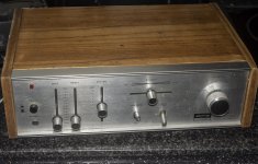
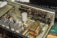
This is a small, simple British amp I just bought cheap. Previous owner had spray painted it black, so I cleaned that off. I've ordered some adapters for the DIN connectors, so haven't been able to listen to it yet, but it does power up and seller said it works great.
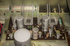
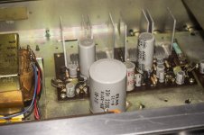
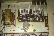
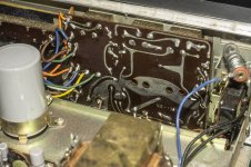
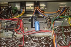
Opened her up and inside is nice and clean, all components are original.
I'm debating whether I should recap this thing, I'll decide after I listen to it play music I guess.
I can't find any info on this amp or a schematic, the design looks similar to the JLH 1969 amp to my eyes.
Anyone know anything about this amp?
Attachments
-
 DSC00094.jpg293.2 KB · Views: 662
 -
 DSC00096.jpg307.8 KB · Views: 612
 -
 DSC00096b.jpg250.6 KB · Views: 623
 -
 DSC00097.jpg538.1 KB · Views: 628
 -
 DSC00098.jpg230.9 KB · Views: 655
 -
 DSC00099.jpg436 KB · Views: 480
 -
 DSC00100.jpg235.5 KB · Views: 418
 -
 DSC00100b.jpg268.9 KB · Views: 422
 -
 DSC00102.jpg306.6 KB · Views: 392
 -
 DSC00101.jpg350.7 KB · Views: 385
2SC1061 50v|3a
Alpha Solid State Stereo Amplifier FA-400 Ampl/Mixer Highgat
It's definitely not 1969. It's a Class A / B amplifier with a quasi-complementary output stage (Dinsdale?).
Alpha Solid State Stereo Amplifier FA-400 Ampl/Mixer Highgat
It's definitely not 1969. It's a Class A / B amplifier with a quasi-complementary output stage (Dinsdale?).
Last edited:
There are FA-300 and FA-400 models too, the FA-300 appears similar but the FA-400 is quite a bit more complex.
I don't know a great deal about amp topologies, the four npn transistors and overall layout reminded me of the 1969 amp, but as I say, I don't know all that much.
I don't know a great deal about amp topologies, the four npn transistors and overall layout reminded me of the 1969 amp, but as I say, I don't know all that much.

I think this is pretty much the same:
JLH - Dinsdale Amplifier
"R Tobey & J Dinsdale published an article "Transistor Audio Power Amplifier" in Wireless World in Nov 1961. This was modified by them in Jan 65. A Retrospect was published by them in WW in Nov 69. The first one is available in Self's site:
The Wireless World Archive
This circuit was adopted to Silicon Planar Transistors by John Lawrence Linsley Hood (JLH) and published in WW in Feb 70. At that time, I made notes and drew the circuit in my note book. I am reproducing below the circuit as well as my notes. I do not remember whether it is a regular article, circuit idea or in Letters to the Editor.
---Modified Dinsdale amplifier for use with Silicon Planar Transistors. Output 10W, 15 ohms or 15W 8 ohms. Suitable for use with either +ve or -ve ht line depending on Transistor type. Amended component values are underlined. Capacitor C5, Diode D1, and Resistors R5, R9, R10 & R12 in the original design are omitted.
The distortion is typically 0.07% at 1 KHz and 10W and the square wave response is free from overshoot or ringing even with capacitive loads upto beyond 20 KHz.
The circuit can be used with -ve HT rail with Tr types shown in table, provided the electrolytic capacitors are reversed. The numbering of the components is that used in the original article in Jan65.
The loud speaker plop on switching on is avoided by DC coupling the NFB to the first transistor via R16. This causes the potential at the loud speaker output to rise fairly slowly as C charges. This arrangement reduces hum pickup on badly smoothed HT supplies...."
I found this fascinating letter from Dinsdale to HiFi World in 1996:
http://ukhhsoc.torrens.org/makers/Leak/Dinsdale_HFNLetter.txt
Full text of a letter published Hi Fi News October 1996 pgs 129 and 131
THE TOBEY-DINSDALE AMPLIFIER (B. 1961)
Dear Sir,
In 1959 Dick Tobey and I were working with the Guided Weapons division of Elliott Brothers (London) Ltd at Borehamwood (which later became part of GEC-Marconi), developing circuitry for inertial navigation systems using discrete germanium transistors (this was pre-silicon and pre-ICs). Searching one day for a 10W wideband power amplifier circuit, we came across an article by Lin [1] in Electronics which described the now well-known 'quasi-complementary' output configuration. Since germanium npn power transistors were unobtainable, we took Lin's basic idea and developed a practical circuit using two pnp output transistors with complementary drivers.
Like many young engineers at that time, we were both very keen on hi-fi. In the late 1950s, all top-end amplifiers used valves; some designs for transistor power amplifiers had been published, but these all required output transformers, sometimes inter-stage transformers as well, and the inevitable phase shifts prevented the application of sufficient feedback to compensate for nonlinearities and other distortion products inherent in transistor circuits of the day. There were a number of good power amplifiers on the market, but the long-established leaders were generally held to be the Leak 'Point One' and the Acoustical 'Quad 22'. I recall that my own equipment consisted then of a Garrard 301 turntable, SME 3009 arm, Decca ffss Mk I pickup, Williamson amplifiers built by myself five years before while still at school and Goodmans dual-concentric loudspeakers mounted on large sand-filled 'infinite baffles'.
Our new transformerless amplifier wasn't in the same league as Leak and Quad; it had a flat frequency response from about 20 Hz to 20 kHz (referred to then as c/s), distortion less than 0.3 % and signal/noise ratio better than 80 dB. But also ˜ joy of joys ˜ it had negligible phase shift throughout and beyond the audible frequency range because it had no transformers. Substituting the prototype into either of our hi-fi systems provided a sound quality which was certainly comparable with that of up-market valve amplifiers and very much better than any of the transistor amplifiers then available. We then developed a simple 2-stage stereo pre-amplifier with all the usual facilities, and again, the overall performance seemed as good as anything we had heard.
We decided to write up our designs for publication, choosing the journal Wireless World both for its reputation and for its generous rates of payment. This last point was doubly relevant for us because in return for appropriate acknowledgement, Elliott Brothers generously paid authors of papers in professional journals a bonus to match the publisher's fee. We also decided, before publication, to apply for provisional patent cover on one aspect of the pre-amplifier: by applying the low-pass filter around the same stage as the Baxandall-type tone controls, the filter slope was modified by the tone controls, increasing with treble boost and thus reducing the tendency for treble boost to increase background hiss.
I also thought at the time that we should have filed a further specification covering our use of a germanium diode between the bases of the complementary driver transistors to control the quiescent current in the output stage; by mounting this diode on the same heat sink as the output transistors, the thermal characteristic of the diode automatically lowered the quiescent current if the heat sink got too hot, thus reducing the chance of thermal runaway. Elliott Brothers not only encouraged staff to publish; they also allowed staff free use of the company's patent agent to help draft specifications. And so, with free professional help we filed our patent application. This point is relevant to what happened later.
Our articles describing the transformerless audio power amplifier and the stereo pre-amplifier were published by Wireless World in November and December 1961 [2],[3], and as expected they caused quite a stir. We received 64 letters from readers, the majority requiring either information on suppliers of the npn transistor or a free fault-finding service, and we were also approached by Henry's Radio off Edgware Road, the doyen of electronic hobby kit and component suppliers, asking us to check and approve their home construction kit which became known as the 'Tobey-DinsdaIe Amplifier'. We negotiated with Sylvania Thorn to make available to hobbyists a cheap npn transistor, the SYLI 750, equivalent to the mil. spec. 2N388A we had used in the prototype, which was after all a strictly for a defence application. Years later, I learned [4] that Thorn sold 484,000 of these transistors, either in ones and twos to hobbyists or in larger quantities to companies for making up into kits. I also learned that our circuit had made redundant many suppliers of output transformers, among them one Max Townshend who had been augmenting his grant as a student in Australia by winding transformers after lectures. I met Max in the late 1970s and we became firm friends in spite of my earlier attempt to cripple his education prospects.
One day, we received a phone call from Harold J Leak inviting us to visit his South London plant to demonstrate our amplifier. On the appointed evening we drove there in Tobey's Mini-cooper (remember them?) to be received by a very affable HJL in person. Most of his employees had finished work for the day, but we met a few senior staff who had stayed on specially for us. After a conducted tour of the factory we were treated to a gourmet dinner, and I recall being impressed by the sound of the company's new 'sandwich' loudspeakers. While HJL was out of the room we inspected the equipment more closely and discovered that each channel was driven by four of his valve amplifiers, which said something about the efficiency of the loudspeakers.
Before we left, HJL complimented us both on our achievement and said that his company's transistor amplifier was under development. He was also most insistent that we left the prototype with him 'for a few days' so that he could carry out some measurements. We emphasised that the cases were not to be opened up, pointing out that we had taken the precaution of sealing all the screws with the official 'tamper-proof' red lacquer used at Elliott Brothers by MoD inspectors. HJL assured us that the cases would remain unsullied, and we returned home well after midnight basking in the glow of a memorable evening.
Two weeks later the prototype amplifier had still not been returned, and it took several phone calls to the company before it reappeared with all of the screws loosened, some missing. Our complaint to HJL was dismissed with a vague apology that his staff 'hadn't followed instructions'. Some time later I read in the audio press that Leak were planning to launch a transistor hi-fi amplifier at the forthcoming Audio Fair, to be held in the Russell Hotel.
One evening I received a phone call at home from a dealer I knew.
'Have you seen Leak's new Stereo 30 amplifier?'
'No, not yet ˜ I'm hoping to hear it at the Audio Fair.'
'It's almost exactly your design - resistor values, everything! The transistors have funny numbers, but they'll be cheap equivalents.'
'How do you know all this?'
'I'm going to stock them in the shop, and they've sent me the servicing booklet. I'll make you a photocopy. '
The copy duly arrived, and it was indeed almost identical to the Tobey-Dinsdale circuit. Now this was naughty. We realised that once the circuit had been published anyone could use it, but we didn't see why Leak should make money at our expense, especially after looking inside without our agreement. And he clearly didn't know about the patent application!
My friends at Wireless World were only too happy to send me a Press pass for the Audio Fair, and I crept into the back of a very crowded Leak room to hear HJL in full flow describing and demonstrating the Stereo 30. After the demo. I joined the enthusiastic crowd around HJL and when I could get a word in I started to complain that he was using our design without acknowledgement. HJL didn't want to listen, until I added: 'I suppose you know that the circuit is patented'. Immediately, his attitude changed. Disentangling himself from the crowd of dealers and reviewers he led me into a side room.
'I'm going to tell you a true story', he said. 'When I was about your age, I was interested in condenser microphones. I did some development work and came up with what I thought was a new idea. I wanted to find out whether my idea was original, so I spent several afternoons at the Patents Office library in Chancery Lane investigating patents on condenser microphones. One day, a man approached me and asked what I was doing, and I said that I had an idea for a new type of microphone. The man then said "I am from Westinghouse, and we are currently the principal world supplier of condenser microphones. If you do anything to rock our boat, we will break you financially; we have far more money than you".'
HJL then looked me straight in the eye and added 'I have far more money than you, and if you rock my boat I will destroy you.'
I was totally devastated by this outburst, and left the room in confusion. Later on, Tobey and I decided that there was probably little we could do without spending quite a lot of time and money, and risking much more, so sadly we dropped the matter.
With hindsight, I realise that I should have replied to HJL, with some degree of truth, 'But Mr Leak, the amplifier patent was prepared by Elliott Brothers, and I fancy that they probably have more money even than you!'
But one only thinks of these things later.
Wireless World published updated circuits in January and February 1965 [5], including working drawings (prepared by myself) showing printed circuits, metal cases and wiring details, which brought me a further postbag of 90 readers' letters. I was disappointed when amplifiers based on the design were marketed (without acknowledgement) by Goodmans and Truvox, but heartened when the US company Daystrom, famous for its range of 'Heathkits', paid me to check and approve their professional kit based on my circuit.
I have already explained that the amplifier was originally designed for the defence industry, and it performed as well for the military as for the hi-fi community. The most memorable mid 1960s, when it was used to control the early experiments with the VTOL engine, which resulted in the Harrier jump-jet aircraft.
There were a number of amusing incidents. On one occasion, the Government Chief Scientist paid an official visit to Elliott Brothers. After the usual tour of the plant he demanded to speak with myself. The company directors had no idea what this was all about, but I was hurriedly summoned from my development bench and told to clean myself up. I arrived at the directors' conference room to find that this illustrious visitor was building my circuit in his spare time and needed some advice! We continued to correspond and, needless to say, he was delighted with his amplifier. Many engineers in industry used their companies' facilities unofficially to manufacture my amplifiers. In one such company ˜ a household name ˜ a small error on their version of the printed circuit resulted in several hundred output transistors being written off. Rather than throw the corpses away, they were linked together to make a 'Dinsdale belt', which was presented to me when I visited the area to speak at a meeting of the IEE.
In conclusion, it can fairly be said 35 years after its inception that the performance of the Tobey-Dinsdale amplifier, while representing a break-through at the time, was no match for the excellent circuit designs which were to follow. Nevertheless, this early work is significant because not only did it draw attention to Lin's important but largely unrecognised work of five years before, but it also demonstrated to a public, largely disenchanted with the poor performance of contemporary transistor amplifiers using output transformers, that sound quality approaching that from valve amplifiers was possible from these devices. Hence this work stimulated a serious reappraisal of the merits of transistors in high quality audio applications, and also paved the way for subsequent work by Bailey, Linsley Hood, Self and many more. Today, 35 years later, I occasionally meet someone who proudly tells me that they used to own a Tobey-Dinsdale amplifier.
Some even claim that it still works, although I suspect that the electrolytics will be rather dry by now.
Jack Dinsdale, Dundee
1. Lin, HC: Quasi-Complementary Transistor Amplifier, Electronics, Sept. 1956
2. Tobey, R and Dinsdale, J: Transistor Audio Amplifier, Wireless World, Now. 1961
3. Tobey, R and Dinsdale, J: High Fidelity Pre-amplifier, Wireless World, Dec. 1961
4. Dinsdale, J: A Design in Retrospect, Wireless World, Nov. 1969
5. Dinsciale, J: Transistor High Quality Audio Amplifier, Wireless World, Jan/Feb. 1965
Last edited:
Explanation of how the circuit works. Schaltungsanalyse einer Quasikomplementärendstufe.
Transistorendstufe in Quasikomplementarschaltung
Transistorendstufe in Quasikomplementarschaltung
Cheers. I'm not sure I understood it all, but certainly useful to read. This sentence makes me think I should replace the electrolytics though:
"Since the energy supply is asymmetrical with only an operating voltage of +40 volts, an output electrolytic capacitor with a large capacity is necessary."
50 year old electrolytics will probably be pretty dry by now, so I expect their is a good chance the value of that large output cap has fallen significantly.
Last edited:
Hmm, looks like a total rebuild of this thing is in order as after testing today, the right channel is dead, both when connected to speakers and through headphones. The left works but doesn't sound too great, lacking a bit in clarity and treble.
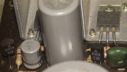
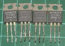
So I may end up replacing all the electrolytics and the output trannies. I can buy replacement 2SC1061s easily but I am sure there is a modern equivalent, they are a pretty standard NPN BJT after all. A modern equivalent will probably sound slightly better too I expect. Anyone got any thoughts on whether it would be best to just put replacement 2SC1061s in or go for an alternative tranny?
So I may end up replacing all the electrolytics and the output trannies. I can buy replacement 2SC1061s easily but I am sure there is a modern equivalent, they are a pretty standard NPN BJT after all. A modern equivalent will probably sound slightly better too I expect. Anyone got any thoughts on whether it would be best to just put replacement 2SC1061s in or go for an alternative tranny?
I googled for modern equivalents and apparently, the TIP31, TIP41 MJE15028 MJE15030 and 2SD526/KSD526 will all work fine.
I probably already have some suitable replacements in my boxes of components, I think there are some TIP31s or TIP41s in my tranny box, I'll have to check.
What I'm wondering, is if a more modern tranny will sound better? I keep reading the supposition that it is the improvement in components that had improved sound quality over time as the designs were already worked out pretty well in the early days of solid state.
W£32 en I was in the trade I used to retail these amplifiers Cheap and chearful would be an apt description about £32 in 1971 they were reliable very few if non warranty claims
Definitely Jap
Our rep for these was a mr Collins he also sold us Harman Kardon
The amplifier was reviewed (bad) by the mags at the time
For me good value would go with a garrard sp25 goldring g850 wharfdale dentons or lintons
for the time a good budget system
Trev
Definitely Jap
Our rep for these was a mr Collins he also sold us Harman Kardon
The amplifier was reviewed (bad) by the mags at the time
For me good value would go with a garrard sp25 goldring g850 wharfdale dentons or lintons
for the time a good budget system
Trev
Thanks for the info Trev.
I ran out of solder, so I haven't started on refurbing this amp yet, first thing I'll do is replace all the electrolytics, I'll probably replace the output trannies too. Hopefulyl that iwll get it working.
I'm wondering if I can make some upgrades to improve it, the power supply arrangements are very basic with just one 2200uF smoothing cap, I am sure I can do better and there is plenty of spare room in the case.
Yes, one look at the chassis with extruded front panel and ISO fasteners tells you its not a British product. The caps, semis and most other components likewise. By the late 1960s, US and Japanese audio manufacturers were in full swing with staggering production numbers for a global consumer audio market of everything from cheap and cheerful to highly complex receivers and multi-channel, high powered affairs. Even the generic types that were "house" branded all looked better than local products, had more features and often sounded better too.
To credit anything that survives from that period to independents like JLH or Tobey and Dinsdale is really a reflection of how little knowledge remains of the work of other specifically British audio pioneers who worked in the industry but effectively were silenced. What we learn now usually comes from only one magazine source or personal anecdotes and those alone aren't enough to give a true picture of what advances were made there, by whom and how they compare with designs from other countries, papers and patents etc. In other words limited sources lead us to parochial, or one-eyed views.
For more general interest, I've been reading the comments of Jim Lesurf, Academic and ex-Armstrong Audio employee who once worked on their products. Also interesting industry stuff and for certain there is much more to learned out there too.....Jim's Audio Pages and Websites
The output stage transistors are Japanese. Radiators are small non-industrial type.
Power transformer, transistors and heat sinks are balanced.
Highgate-Dufay
38 Jamestown Road, London N.W.1, England
Manufacturer of Electronics for photography.
Highgate-Dufay; London manufacturer in GB, Model types from
Power transformer, transistors and heat sinks are balanced.
Highgate-Dufay
38 Jamestown Road, London N.W.1, England
Manufacturer of Electronics for photography.
Highgate-Dufay; London manufacturer in GB, Model types from
Last edited:
I'm ready to start work on this amp now and wondering how to approach it.
Should I replace all the electrolytics and the output trannies than see if it works, or should I start by trying to diagnose the issue with the dead channel?
What would be the best choice to use for the output trannies? I.E. is there a more modern alternative to the Hitachis currently fitted that sound better, has lower noise etc?
This is not the Grail 🙂 The construction was standard for its time. The schematic can be obtained by reverse engineering. Measure the supply voltage. Power = V ^ 2 / 8R. I think it will be 10-15 W RMS.
Replace large capacitors in the power supply unit and at the output with similar ones. The serviceability of the channel can be determined by applying a signal to the input on the board. Compare measurements of good and bad. Take the transistors from the craft box. Check all output transistors in the faulty channel. Be careful about types and pinouts.
Replace large capacitors in the power supply unit and at the output with similar ones. The serviceability of the channel can be determined by applying a signal to the input on the board. Compare measurements of good and bad. Take the transistors from the craft box. Check all output transistors in the faulty channel. Be careful about types and pinouts.
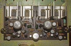
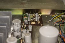
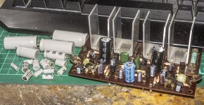
I removed the main board and replaced all the electrolytic caps, luckily I had all the right values in my stash. Tomorrow I'll removed the output trannies. Not sure what I will replace them with, need to root in my box and see what I have. I might have to order some suitable replacements. I also replaced two electrolytics on the underside.
The big cap next to them is a 2200uF and I think it's the smoothing cap for the power supply. I don't have a 2200uF cap to replace it, is there any reason I can't use a 4700uF or 6700uF instead as I have those. Or what about replacing the single 2200uF cap with a bank of caps, there is room to fit a bank and wouldn't that be an improvement in smoothing the supply current?
The big cap next to them is a 2200uF and I think it's the smoothing cap for the power supply. I don't have a 2200uF cap to replace it, is there any reason I can't use a 4700uF or 6700uF instead as I have those. Or what about replacing the single 2200uF cap with a bank of caps, there is room to fit a bank and wouldn't that be an improvement in smoothing the supply current?
Attachments
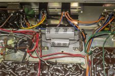
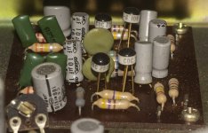
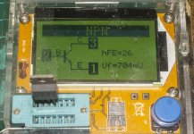
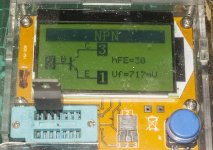
I pulled the four output trannies and tested them, all four work and have the following values:
hFE Vf
38 703mV
26 704mV
30 717mV
44 704mV
That's quite a disparity in gain, is it likely that the gain has changed over time, or did they just not bother to match the trannies when they built the amp?
With all four of the output trannies working, the dead channel fault must lie elsewhere, which might be a PITA to find and fix.
I went through my box of trannies and I have all manner of power MOSFETs but a paltry choice of NPN BJTs. The only one I do have that are likely suitable are SEMELAB parts, no model number on them as they are production samples that should never have left the factory. I don't remember exactly what the explanation for what they are was now, but I had an email discussion about them with SEMELAB.
I have 11 of them and they measure quite consistently, I could make a set of four that all had a hFE of 28 with the Vf varying between 717 and 723mV.
But is a gain of 28 high enough, given the originals vary between 26 and 40? Would it be better to use trannies with a gain of 40 or more?
Attachments


Check the small TO-92 transistors. If there is 1/2 supply voltage on one side of the large capacitor, the channel may be working. This could be a pre-amp, phone jack, regulators, or switches.
Measurements of power transistors at low currents may be unreliable. Over the past 50 years, transistors could get better 🙂
Measurements of power transistors at low currents may be unreliable. Over the past 50 years, transistors could get better 🙂
Last edited:
- Home
- Amplifiers
- Solid State
- 1971 Highgate Acoustics Alpha FA-200